background image

OnAir 2000M2 Digital Mixing Console

Date printed: 12.11.03

SW V 4.0

Intro  1-3

PPM

BARGRAPH

VCA

BARGRAPH

PPM

DIM

DIM

DIM

DIM

DIM

DIM

VCA

ANALOG

DIGITAL

VCA

VOL CONTR

VOL CONTR

VOL CONTR

REGENSDORF
SWITZERLAND

+

+

+

+

AUX1 MASTER

AUX2 MASTER

+

+

C TALK

C TALK

+

+

+

+

+

+

A

D

D

A

D

D

A

D

A

D

A

D

D

A

A

D

(

Σ

 ON AIR/D)

(

Σ

 ON AIR/A)

Σ

 RECORD/A

N–1 A

N–1 F *

+

+

+

+

+

+

+

+

+

+

+

+

+

+

+

+

+

+

+

OFF AIR

a

EXT 1

a

EXT 3

a

EXT 2

a

EXTERN MONITORING

d

a

a

a

a

a

+

C+S TALK

+

+

PFL/TB

AUX 2

AUX 1

DJ

GUESTS

CR. SPKR

STUDIO SPKR

STUDIO

+

STUDIO CUT

C.R. CUT + DIM

MONO

STUDIO MONITOR

MAIN OUTPUTS

METER 2

C.R./ DJ MONITOR

MONO

C.R.MON.

CR/PFL

PFL

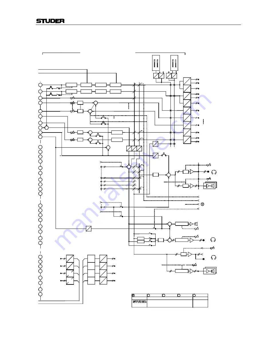
MASTER AND MONITORING

09.07.01STI

On-Air 2000M2 V4.0
BLOCK DIAGRAM AUDIO

+

+

+

+

+

+

+

+

d

d

d

RET 3

RET 2

d

d

D

D

SFC

D

SFC

D

RET 1

a

A

D

D

D

d

A

D

A

D

a

a

SEND 2

SEND 4

SEND 1

SEND 3

D

D

d

a

A

D

RET 4

4 x INSERTS

(OPTIONAL)

METER 1

(INSERT)

(INSERT)

+

EXT TO PFL

C+S TALK

TB TO STUDIO

D

A

A

D

A

D

D

D

+

A

D

EXT PFL

a

D

A

TB TO C.R.MON

TB TO C.R.MON

STUDIO MIC SIGN.

MIC SIGN.

TB TO TEL

MONITOR SELECT

A

D

Σ

 AUDITION

D

D

d

d

(OPTIONAL)

D

D

D

D

D

A

METER INTERFACE

EXT PFL CONTROL

LIMITER

LIMITER

LIMITER

LIMITER

LIM

LIM

LIM

LIM

Σ

 PROGRAM

Σ

 PROGRAM/A

(INSERT)

(INSERT)

SEND

RETURN

Σ

 FADER **

a

+

PFL**

PFL**

a

EXT TB INPUT

EXT TB TO STUDIO

EXT TB TO CR

EXTERN TB INPUT

(OPTIONAL)

WITH OPTION N-1 C...F, ONLY TWO STEREO INSERTS AVAILABLE

Σ

 FADER **

N–1 A

N–1 F*

Σ

 AUDITION

Σ

 RECORD

Σ

 PROGRAM

Summary of Contents for OnAir 2000M2

Page 1: ...ixing Console SW Version 4 0 4 02 1 Part One Operating Instructions 2 Part Two Service Instructions 3 Part Three Diagrams Center Section 4 Part Four Diagrams Fader Section 5 Part Five Accessories Operating and Service Instructions ...

Page 2: ...tuder Professional Audio GmbH Technical Documentation Order no 10 27 4526 Ed 0804 Printed in Switzerland Althardstrasse 30 CH 8105 Regensdorf Switzerland http www studer ch Subject to change Studer is a registered trade mark of Studer Professional Audio GmbH Regensdorf ...

Page 3: ... expressly marked on the product If a special design should be covered by a higher class of this standard the device concerned will be marked directly on the assembly or sub assembly in accordance with the above standard A1 First Aid In Case of Electric Shock Separate the person as quickly as possible from the electric power source By switching off the equipment By unplugging or disconnecting the ...

Page 4: ...nal part of the design and must not be blocked in any way during operation e g by objects placed upon them or placement of the unit on a soft support The unit must not be heated up by external sources of heat radiation sunlight spot lights B3 Earthing and Power Supply Earthing of units with mains supply class I equipment is performed via the protective earth PE conductor integrated in the mains ca...

Page 5: ...x planation at the beginning of this paragraph B4 Electromagnetic Compatibility EMC The unit conforms to the protection requirements relevant to electromag netic phenomena that are listed in the guidelines 89 336 EC and FCC part 15 The electromagnetic interference generated by the unit is limited in such a way that other equipment and systems can be operated normally The unit is adequately protect...

Page 6: ...using e g metal foil underneath the floor covering carpet with conductive backing C Maintenance All air vents and openings for operating elements faders rotary knobs must be checked on a regular basis and cleaned in case of dust accumula tion For cleaning a soft paint brush or a vacuum cleaner is recommended Cleaning the surfaces of the unit is performed with a soft dry cloth or a soft brush Persi...

Page 7: ...ergized parts For this reason the following precautions must be observed Maintenance may only be performed by trained personnel in accordance with the applicable regulations The equipment must be switched off and disconnected from the AC power outlet before any housing parts are removed Even if the equipment is disconnected from the power outlet parts with hazardous charges e g capacitors picture ...

Page 8: ... volume of waste If you need to dispose of the transport packing materials please try to use recyclable means Disposal of Used Equipment Used equipment contains valuable raw materials as well as materials that must be disposed of professionally Please return your used equipment via an authorized specialist dealer or via the public waste disposal system en suring any material that can be recycled i...

Page 9: ...own expense Caution Any changes or modifications not expressly approved by the manufacturer could void the user s authority to operate the equipment Also refer to rele vant information in this manual G2 CE Declaration of Conformity We Studer Professional Audio GmbH CH 8105 Regensdorf declare under our sole responsibility that the product Studer On Air 2000 Digital Mixing System starting with seria...

Page 10: ...ler than 70 C Average heat increase of the cooling air shall be 20 K allowing for an additional maximum 10 K increase at the hot components In order to dissipate 1 kW with this admissible average heat increase an air flow of 2 65 m min is required Example A rack dissipating P 800 W requires an air flow of 0 8 2 65 m min which corresponds to 2 12 m min If the cooling function of the installation mu...

Page 11: ... In such a case the absolute humidity must be so low that the relative humidity related to the coldest system surface always remains below 100 Ensure that the enclosed air is as dry as possible when powering off i e before switching off in winter aerate the room with cold dry air and re move humid objects as clothes from the room These relationships are visible from the following climatogram For a...

Page 12: ...ontaminants Recommended application temperature range is 20 40 C Remove the plastic protective backing from the rear side of the clamp and apply it firmly to the surface at the desired position Allow as much time as possible for curing The bond continues to develop for as long as 24 hours For improved stability the clamp should be fixed with a screw For this purpose a self tapping screw and an M4 ...

Page 13: ...tem and or its options at the time of delivery to the Customer but have not been developed by Studer The following conditions are applicable to programs of third parties The right to use third parties programs is governed by the License Agreement attached hereto if applicable which is an integral part of this Agreement The Customer shall sign any and all License Agree ments for all further program...

Page 14: ...ding to the paragraph above by appro priate defense measures against unauthorized access This obligation of non disclosure is a perpetual obligation Third parties are entitled to have access to the License Material if they use the License Material at the Customer s site in compliance with this Agree ment Under no circumstance are third parties entitled to have access to the in stallation software ...

Page 15: ...ing and the key is illuminated until any other Monitoring Selector key is pressed Mutually Releasing Momentary If one of the Monitoring Selector keys is pressed for longer than 0 2 s it acts as a momentary key The former monitoring source selection is can celed and the new monitoring source selection becomes active Upon re leasing the key the former monitoring source selection is reactivated Uhm T...

Page 16: ...al REC signaling output has been provided on pin 9 of the SIGN connector formerly labeled as Spare OUT to extend the on air signaling features SIGN D type 9 pin male Pin Signal Pin Signal 1 5 V SUPPLY 6 COMMON 2 ON AIR IN 7 Spare IN or Ext CR DIM IN 3 CR MIC OUT 8 STUDIO MIC OUT 4 PGM OUT 9 REC OUT 5 GND depending on Customer Code setting For the ON AIR INDICATION setting on the COMMON SETTINGS pa...

Page 17: ...e dimming of the studio monitor speakers during talkback from the control room to the studio Code 0x00002000 Used to swap the functions of the PFL and the OFF keys next to the faders regardless whether they are used for the standard PFL and OFF functions or whether other functions are configured for any of these keys Basic information on this subject to be found in chapter 9 Operating In struction...

Page 18: ...Specifications 2 3 3 Operating Concept 3 1 3 1 Operating Elements 3 2 3 1 1 Power Switch 3 2 3 1 2 Central Section Display Unit 3 3 3 1 3 Central Section Meter Unit 3 3 3 1 4 Central Section Monitoring and Talkback 3 4 3 1 5 Fader Units 3 6 4 Channel Functions 4 1 4 1 Keys 4 1 4 2 Faders 4 1 4 3 Overload Indicator 4 1 4 4 Channel Screen 4 2 4 4 1 Channel Screen Fields 4 2 4 4 2 Multi Source Select...

Page 19: ...m Memory 5 15 5 8 3 Save a Channel Routing to Memory 5 15 5 8 4 Delete a Channel Routing from Memory Administrator Only 5 16 5 8 5 Channel Routing Administration 5 16 5 9 Using PC Cards 5 17 5 9 1 Load a Snapshot Mic Setting Channel Routing from PC Card 5 17 5 9 2 Save a Snapshot Mic Setting Channel Routing to PC Card 5 18 5 9 3 Delete a Snapshot Mic Setting Channel Routing from PC Card 5 18 5 10 ...

Page 20: ...4 CTRL OUT1 2 CTRL IN Application Examples 9 5 10 Automation 10 1 10 1 Introduction 10 1 10 2 Features of the OnAir 2000M2 CAB Support 10 1 10 3 Application Handling 10 2 10 3 1 Configuration for Automation Control 10 2 10 3 2 Communication Time out 10 2 10 3 3 Output Selection 10 3 10 3 4 Start a New Title from Schedule 10 3 10 3 5 Indication of the Currently Playing Input Line 10 4 10 3 6 Pre Li...

Page 21: ... Extension Optional 12 14 12 2 12 Customer Code 12 17 13 SW Update 13 1 13 1 Software Structure 13 1 13 1 1 The CPU Software Package 13 1 13 1 2 DSP Software Package 13 1 13 1 3 Important Information for Software Update to V4 0 13 1 13 2 SW Update Procedure 13 3 13 2 1 Error Handling 13 5 14 System Diagnostics and Error Handling 14 1 14 1 Error Warning and Information Messages 14 1 14 1 1 System D...

Page 22: ...dule 15 10 15 12 Digital Insert Module 15 11 15 13 Monitoring Module 15 12 15 14 Monitoring Module w Extension 15 18 15 15 Serial Interface Module 15 21 15 16 Clock Sync Module 15 21 15 17 Time Sync Module 15 22 16 DIP Switches and Jumpers 16 1 16 1 Input Modules Mic Line Digital 16 1 16 2 TB Mic Input Module 16 2 16 3 Telephone Hybrid Interface 16 5 16 4 Analog Output Module 16 5 16 5 Dual Analog...

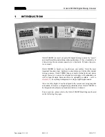
Page 23: ...are control elements Unlike other digital mixing consoles OnAir 2000M2 does not need external racks and power supply however versions for external power supply with redundancy as well as Input Module Extension Box are optionally available refer to chapter 5 8 Everything is integrated in a single lightweight console Since it is fully digital it can be adapted to the current user using snapshot auto...

Page 24: ...F AF PF AF PF AF a a a a a TAPE 1 TAPE 2 TT 1 TT 2 EXT 1 EXT 2 ANALOG INP WITH 6 CH SELECTOR OPTION a a EXT2 EXT1 TT 2 a a a D A TT 1 TAPE 1 TAPE 2 a a a a a HL INP 3 HL INP 4 CTRL I O CTRL I O CTRL I O CTRL I O XLR CONNECTOR D TYPE CONNECTOR DIN MULTIPIN 39p BANTAM JACK AUX 2 AUX 1 N 1 A N 1 F Σ AUDITION Σ RECORD Σ PROGRAM HEADPHONE JACK SOCKET CTRL I O CTRL I O CTRL I O CTRL I O CTRL I O CTRL I ...

Page 25: ... PFL PFL MASTER AND MONITORING 09 07 01STI On Air 2000M2 V4 0 BLOCK DIAGRAM AUDIO d d d RET 3 RET 2 d d D D SFC D SFC D RET 1 a A D D D d A D A D a a SEND 2 SEND 4 SEND 1 SEND 3 D D d a A D RET 4 4 x INSERTS OPTIONAL METER 1 INSERT INSERT EXT TO PFL C S TALK TB TO STUDIO D A A D A D D D A D EXT PFL a D A TB TO C R MON TB TO C R MON STUDIO MIC SIGN MIC SIGN TB TO TEL MONITOR SELECT A D Σ AUDITION D...

Page 26: ...BU in puts on XLR connectors and two S PDIF inputs with Cinch and optical TOSlink connectors available Analog Hex Line Input Modules have six stereo inputs on 39 pin Siemens connectors while the Digital Hex Input Modules have six AES EBU in puts on 39 pin Siemens connectors as well Each input of an input module is equipped with control inputs and outputs GPIO used for fader start mute signaling et...

Page 27: ...ansported 2 2 2 Installation Primary Voltage The power supply unit is auto ranging it can be used for mains voltages in a range of 100 to 240 VAC 50 to 60 Hz General Precautions Do not use the unit in conditions of excessive heat or cold near any source of moisture in excessively humid environments or in positions where it is likely to be subjected to vibration or dust The ambient temperature rang...

Page 28: ... Please ask your nearest Studer representative 2 2 4 PC Card The OnAir 2000M2 mixing console is equipped with a PC Card socket Using the industry standard SRAM PC Cards the user can save important console information on a card This information can then be used to restore the console to the same state at a later moment Since the information stored on the card is DOS compatible it is easily transfer...

Page 29: ... figure typ 4 dB max gain bandwidth 20 kHz Rs 200 Ω Common mode rejection 50 dB 15 kHz 75 dB 50 Hz Line Level Inputs Analog line level input modules are available in three versions Stereo input with A B switching balancing transformer XLR connectors Stereo input with A B switching electronically balanced inputs XLR connectors Stereo input with 6 input selector balancing transformer On this module ...

Page 30: ...ed to two XLR sockets with individual buffers Output level 2 to 5 V Output impedance 110 Ω Equalizer Treble control High 5 kHz 10 kHz 15 dB depending on Customer Code setting refer to 12 2 12 Equalizer Mid 200 Hz to 10 kHz 15 dB Bass control Low 200 Hz 400 Hz 15 dB Crosstalk Attenuation Between channels 90 dB Input fader attenuation 100 dB Power Supply Mains voltage 100 to 240 V 50 60 Hz auto rang...

Page 31: ... 8 2 0 785 445 2 8 5 338 275 3 15 758 793 1982 6 1432 881 4 592 314 256 1007 456 5 1557 6 821 side panel 2 mm 940 5 7 866 7 2 8 5 2 0 308 7 m o d u le s p a c e s 7 m o d u le s p a c e s 7 m o d u le s p a c e s 7 m o d u le s p a c e s 11 module spaces MONITORING POWER SUPPLIES VENTS VENTS VENTS VENTS A A ...

Page 32: ... off On the screen above the fader strips the new settings are immediately updated The OnAir 2000M2 concept has all current settings for every channel visible at any time This innovative user surface is called the Touch n Action concept and is patented by Studer In broadcast applications many DJs and operators without a special techni cal education work on the same mixing console Every DJ has his ...

Page 33: ...ir 2000M2 is equipped with the optional dual external power supply for redundancy no power switch is at the rear of the console In stead each of the two power supply units has its own power switch Please note that the two external power supply units should be connected to different phases of the mains for improved redundancy For operation and service details of the external power supply units an a...

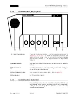
Page 34: ...Encoders Depending on the current status the rotary encoders are used for parameter settings 3 Contrast Knob For setting the LC display contrast depending on the desired viewing an gle and the ambient light conditions 4 User Stopwatch Control Keys to control the user stopwatch lower Refer to chapter 5 13 5 Loudspeaker for PFL and talkback signals 3 1 3 Central Section Meter Unit The central meter ...

Page 35: ... External analog input signal OFF AIR External analog input signal e g tuner for off air listening 2 CR Monitor Speaker Control MON Monitoring volume control DIM If pressed the monitor speaker level is reduced by 20 dB The DIM function is activated automatically if one of the TALK BACK keys is pressed If CR DIM WHEN AUDITION SEL is active details refer to chapter 12 2 2 the monitoring source is AU...

Page 36: ...headphones signal is the same stereo signal as selected by the moni toring source selector 1 It is however not affected by the DIM and CUT functions 5 Talkback Selector for five talkback targets N 1 B N 1 A Connection between the DJ microphone in the control room and the cor responding cleanfeed N 1 output this allows talking e g to the con nected telephone hybrid s or communication lines AUX 2 AU...

Page 37: ... concerning fader start control please refer to chapters 9 14 3 and 15 1 4 PFL key no 1 Key for activating deactivating the PFL pre fader listening function 5 OVL Channel overload indicator 6 Contrast Knob For setting the contrast of the LC display located above the fader panel depending on the desired viewing angle and the ambient light conditions 10 0 10 20 30 40 50 60 OVL PFL ON OFF OVL PFL ON ...

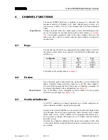
Page 38: ... LOCATE 4 PFL ON OFF NEXT For details on the configuration see chapter 9 4 2 Faders Since the audio path is fully digital the signal does not pass through the faders Therefore linear track mono faders are used The stroke length is 104 mm When opening the fader fader start or signaling commands can be released depending on the configuration see chapter 9 Master Faders Any of the faders can be confi...

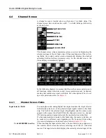
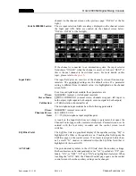
Page 39: ...et up access permission refer to chapter 11 4 4 1 Channel Screen Fields Input Selector Field For microphone and analog digital line input modules the Input selector field directly selects one of two physical input signals routed to this fader strip The field of the selected input is highlighted and the source name appears in the source label field While the channel is active i e channel ON fader o...

Page 40: ...swapped left input to both outputs right input to both outputs or mono signal to both outputs Calibration 15 dB deviation of nominal level The microphone input modules have the following parameters Phase NORM INV normal or inverted Phantom Power 48 V OFF 48 V ON Gain 5 75 dB microphone input amplifier gain A touch on the Input field does not change a parameter but opens the Channel Control page on...

Page 41: ... For this purpose just touch the desired channel s source label Only one source label can be highlighted at a time The tag is auto matically removed when the fader of this channel is opened while the channel is ON This function has no influence neither on control output signals nor on the internal functionality of the console 4 4 2 Multi Source Selector Page The SOURCE SELECTION page on the centra...

Page 42: ...IN The microphone preamp s gain is set with the first rotary encoder in a 5 75 dB range the adjusted value is indicated in the GAIN field AUX 1 AUX 2 The AUX 1 2 ON and OFF touch screen fields route the channel signal to the corresponding auxiliary bus if ON is selected and highlighted The AF PF touch screen fields allow selection whether the signal is taken after AF or pre fader PF The current se...

Page 43: ...touch screen field INV is highlighted Touching NORM de activates the phase inversion Only in the RR case the phase inversion takes place in the R input path CAL In the CAL field the gain deviation referred to nominal level setting is dis played max deviation 15 dB adjustment with the first rotary encoder AUX 1 AUX 2 The AUX 1 2 ON and OFF touch screen fields route the channel sig nal to the corres...

Page 44: ...r 11 of the user currently logged in the functions not available to this user will not be displayed on the Channel Control page an example is given below This user cannot ac cess the following parameters PHASE AUX 1 Output summing busses ΣPROGRAM ΣRECORD PAN BAL If the user has no access permission at all the Channel Control page will not be displayed ...

Page 45: ...ving type filter with two selectable turnover frequencies and variable boost cut The frequency is selected by the left hand CUTOFF touch screen fields the gain is set with the leftmost ro tary encoder The next rotary encoder sets the frequency of the mid frequency section which is a peaking type filter The third rotary encoder controls the mid frequency gain The rightmost rotary encoder controls t...

Page 46: ...if the EQ Filter touch screen field on the channel screen is touched provided that the selected input module is an analog line or digital input If the user has no access permission to the EQ parameters the EQ Filter page will not be displayed at all The only difference between the analog line digital and the microphone EQ Filter pages is the missing HPF high pass filter switch on analog line digit...

Page 47: ...rk in his own environment he must log in He has to touch the LOGIN field on the central screen The LOGIN page will appear where the user can touch the field with his own name More information on the login procedure can be found in chapter 11 5 After having logged in the LOGIN field changes to LOGOUT when the user leaves the console this field must be used After having touched LOGOUT a dialog box a...

Page 48: ...r rent status The AUX 1 and AUX 2 gain indication symbols are always displayed even if no output module is installed for AUX 1 and or AUX 2 INSERTS On the same page the four insert points can be assigned Assignment is possible to any of the following signals Input CH1 to input CH24 PROGRAM bus RECORD bus Talkback to Studio and or Control Room output if an optional TB Mic Input Module is installed ...

Page 49: ...r be used as a special stereo monitoring bus for information on the special CUT and DIM conditions please refer to chapter 12 2 2 CR DIM WHEN AUDITION SELECTED or as a third mono or stereo clean feed If the user has no access permission for the clean feed and or audition bus parameters there will appear a text next to the corresponding field telling the user that he cannot modify the parameters Th...

Page 50: ... to chapter 16 5 For the Digital Output Module this selection is not required For bus assignment on the Dual Analog Output Module jumper set ting also refer to chapter 16 5 plug the jumper for output A to position OUT1 the jumper for output B to position OUT2 Then the four N 1 signals are output on the following connectors N 1C on output A left channel N 1D on output A right channel N 1E on output...

Page 51: ...puts is possible 5 4 Studio Monitoring The STUDIO MONITORING SOURCE page is opened by touching the STUDIO MON field This page allows selecting one of six signals to be routed to the studio monitoring loudspeakers and headphones This selec tion can also be done via a pushbutton remote control from the studio op tional accessory Studio Talkback Box available The field of the cur rently selected sign...

Page 52: ...accessible in the CHAN ROUT area If no global channel routings should have been defined by the system adminis trator the CHAN ROUT area is not displayed as shown below The right part of the Mixer Setup page also provides the following com mand fields PRIVATE GLOBAL Users can select between private and global snapshots and mic settings SYSTEM CONFIG This field leads to the second level of mixer set...

Page 53: ...apshots can be saved on a PC Card refer to chapter 5 8 and loaded from the card into the console s flash memory if required A name can be given to every snapshot which is displayed in the leftmost field column Also refer to chapter 5 10 1 for information on snapshot access rights 5 6 1 Recall a Snapshot from Memory Select a snapshot by touching one of the name fields The name of the selected snaps...

Page 54: ...age without saving the new name When touching ENTER the keyboard page is left and the snap shot data are saved Note Global snapshots can be saved by the system administrator only Logged in users only can save their private snapshots 5 6 3 Delete a Snapshot from Memory When saving a snapshot the previously saved snapshot data are overwrit ten A snapshot can be deleted too without overwriting it wit...

Page 55: ...ouch field columns on the Mixer Setup page 5 7 1 Recall a Mic Setting from Memory To recall a mic setting from the console s internal flash memory first open the Mixer Setup page by touching the MIXER SETUP field then select a microphone input channel by touching its label field in the channel screen followed by the corresponding field in the MIC SET area The name of the selected mic setting is hi...

Page 56: ...a name assigned can be selected It will however be overwritten by the new mic setting Now a new name can be generated or the already present name can be overwritten or edited When touching ENTER the mic setting data and its new name are saved 5 7 3 Delete a Mic Setting from Memory When saving a mic setting the previously stored data are overwritten A mic setting can be deleted too without overwrit...

Page 57: ...console can be equipped with 6 12 18 or 24 fader strips 1 4 fader modules and with the same number of input modules with A B inputs or hex inputs installed in the console The Input Module Extension Box optionally available allows to increase the number of input modules for smaller console versions The following combinations are allowed No of Fader Strips No of Input Modules No of Extension Boxes 6...

Page 58: ...d above the two rotary encoders as well as the type of the selected input module MIC ANALOG DIGITAL and the po sition of the currently selected fader Above the input module to fader strip assignment the input labels are displayed For hex input modules the left box shows left and right arrows for selection and the right box displays the current label out of the six The channel routing relates to th...

Page 59: ... the fader screen the channel section of a channel routed to the background is either blank or it displays a mas ter fader All channels currently routed to the background can be displayed in the CHANNEL ON OFF page this page is selected by touching CHN ON OFF in the HOME page When routing an input module signal to the background the audio path remains open and the audio passes through the console ...

Page 60: ... is loaded or when a user logs in the input module to fader strip assignment is modified In this moment the audio level of an input signal may not correspond to the physical position of the new fader As the OnAir 2000M2 does not feature motorized faders the Auto Takeover symbol is displayed in the corresponding channel section of the fader screen By moving the fader knob up or down in the indicate...

Page 61: ...MORY or PRIVATE only one user channel routing can be recalled for logged in users by selecting RECALL USER ROUTING When the console is switched on the last channel routing i e the one that was active before power off is automatically loaded 5 8 3 Save a Channel Routing to Memory After having configured the channel routing as desired see chapter 5 8 1 touch the APPLY field The new channel routing i...

Page 62: ... saved or edited by any user not logged in i e the default user if access permission is given Channel Routings User Channel Routing The procedure for the system administrator changing a user s channel routing is described in chapter 5 10 2 Global Channel Routings Five globally accessible channel routings can only be created by the ad ministrator allowing users to set up the channel routing for spe...

Page 63: ...atically The relationship between the file name extension and the file content is shown in the following table Data type File name extension Global snapshot gss Private snapshot pss Global mic setting mis Private mic setting mip Global channel routing gfm 5 9 1 Load a Snapshot Mic Setting Channel Routing from PC Card To load a snapshot a mic setting or a global channel routing from a PC Card touch...

Page 64: ...er confirmation be overwritten it will no more be visible for the initial user If the card is full a dialog box appears telling that the file cannot be saved 5 9 3 Delete a Snapshot Mic Setting Channel Routing from PC Card To delete a snapshot a mic setting or a channel routing from the PC Card DELETE CARD must be touched The page below is displayed please note that the CHAN ROUT area is only disp...

Page 65: ... is not logged in i e he has not entered any password he is automatically treated as the default user The default user too has private settings these will however not be password protected so they can be overwritten by any other user that is not logged in to the console Global parameter settings can be recalled by any user but modified by the system administrator only Access Rights Global Snapshot...

Page 66: ...r s data No other actions on the console can be affected Snapshots and Mic Settings After selecting PRIVATE in the Mixer Setup page the second rotary en coder from the left the one below the user s name label allows to select the user s name In this mode the system administrator can LOAD RECALL SAVE or DELETE all the data being displayed Channel Routing With RECALL USER ROUTING the system administ...

Page 67: ...s user channel routing in the Mixer Setup page after selection of PRIVATE only one user channel routing can be recalled by selecting RECALL USER ROUTING for more information on this sub ject please refer to chapter 5 8 2 Should the user have access permission to the system configuration and or channel routing the corresponding SYSTEM CONF ROUTING fields would be displayed here as well A user can d...

Page 68: ... by the system administra tor Refer to chapter 11 for details on how to set up function access per mission and new user accounts 5 12 System Configuration System configuration is a separate function group which can be accessed only by the system administrator or by users having access permission It is separately described in detail refer to chapter 12 ...

Page 69: ...tch displays and func tions is shown 5 13 1 Watch The watch gives a time day of week and date display The normal time reference is an internal battery buffered real time clock RTC The RTC continues to run even when the console is switched off Therefore it is un necessary to set the watch at power up The RTC can also by synchronized by an optional Time Sync Module connected to the control module bu...

Page 70: ... MIXER SETUP SYSTEM CONFIG INPUT menu item TIMER START YES NO The counter stops when the audio channel that has started the stopwatch is switched OFF or its fader is closed Note If more than one audio channel has caused the fader stopwatch to restart only the last audio channel s time is displayed 5 13 3 User Stopwatch The user stopwatch is located just below the fader stopwatch It is con trolled ...

Page 71: ...ith the HOME field External MUTE and Monitora control for the channel is still available In such a case this channel may also be used as a talkback mic input channel please note that the TB SOURCE parameter of this input must then be set to CR in the INPUT CONFIG page Specifications In the audio path the master fader s is are located before the insert points also refer to the block diagram in chap...

Page 72: ...s is required it is possible to enter this offset in the DEFAULT MASTER LEVEL window on the COMMON SETTINGS page in a range of 7 5 dB The level offset for a master output becomes active when the correspond ing master output is de assigned from a fader strip Important This setting may directly affect the level of the main output signals Please be careful when changing this parameter ...

Page 73: ...AUX 1 X X AUX 2 X AUDIT X N 1 A For configuration details refer to chapter 12 2 4 6 1 Standard Level Meters The following level meters can be installed as standard Digital input Dual bar graph PPM with correlator RTW 11519D STU Stereo display dual PM with correlator RTW 1069 STU Analog input Dual bar graph PPM with correlator RTW 1119E STU Dual bar graph PPM Studer 1 913 611 Dual bar graph VU Stud...

Page 74: ...t SREC is illuminated if selected Program output on air Output signal of the on air master output SPGM is illuminated if selected PFL PFL sum PFL is illuminated if selected External 3 General purpose analog stereo input signal EXT3 is illuminated if selected External 2 General purpose analog stereo input signal EXT2 is illuminated if selected External 1 General purpose analog stereo input signal E...

Page 75: ... monitor speakers by 20 dB by an external signal for this purpose the corresponding Customer Code must be activated too see chapters 12 2 12 and 15 13 for details The signal on the PFL bus is reproduced by the console s built in speakers mono The same speakers are used for talkback The volume is adjusted with the PFL TB potentiometer For monitoring purposes a headphones connector is provided below...

Page 76: ...channel The normal monitoring signal is muted for as long as any PFL keys are active Key Function Description PFL to MONITOR The PFL signal is routed to the monitor speakers if PFL on any channel is active If no PFL is se lected the monitoring signal is the stereo CR signal as selected PFL MON is illuminated if active A volume control knob PHONES adjusts the headphones listening level ...

Page 77: ...ernal Off air input General purpose input signal usually from re ceiver OFF AIR is highlighted if selected EXT 3 External input General purpose input signal EXT 3 is highlighted if selected As soon as one of the fields is touched the corresponding signal is routed to the studio and the field is highlighted The monitoring source selection can be controlled from the studio via ex ternal pushbuttons ...

Page 78: ...d as a third Cleanfeed bus N 1 C The DJ microphone usually is the source for talkback from the CR For mixing consoles with less than 24 channels a separate talkback micro phone is optionally available including preamplifier limiter and A D converter Its main application is in production and editing control rooms where no DJ microphone is required for details refer to chapter 15 6 The parallel stud...

Page 79: ...oth AUX1 and AUX2 keys simultaneously then also illuminates the F1 key 7 3 2 Talkback Settings Starting with SW V3 0 talkback and signaling can be configured inde pendently The SIGN setting formerly labeled MIC LOCATION in the INPUT CONFIG page is used only for signaling red light and moni toring cut and dim The additional TB SOURCE parameter in the INPUT CONFIG page sets the assignment of the tal...

Page 80: ...eenshots When installing an optional TB Mic Input module two different cases must be distinguished Console configuration TB Source Signaling TB Mic Input module within channel configuration e g input module no 13 of an 18 input module console configurable configurable TB Mic Input module outside channel configuration e g input module no 13 of a 12 input module console must be set to CR else no fun...

Page 81: ... be activated by a dedicated control input on the EXT PFL CTRL connector refer to chapter 15 13 With this feature the OnAir 2000M2 is well suited for the integration with a broadcast automation CAB computer assisted broadcasting system These systems need a separate PFL input that can be activated by the CAB system itself Key Function Description External PFL Switches the EXT PFL OUT control output...

Page 82: ...open assigned to program or record bus corresponding master fader open STUDIO MIC OUT At least one input of a studio microphone is active channel ON fader open assigned to program or record bus corresponding master fader open PGM OUT Depending on ON AIR INDICATION condition selected in the COMMON SETTINGS page ΣPROGRAM AND ΣRECORD at least one channel is active channel ON fader open assigned to pr...

Page 83: ... the output signals depends on the control elements of the fader strip keys 1 to 3 fader input selection channel routing and output bus assignment as well as on the console configuration Each channel consists of either two A B input module or six hex input module audio inputs Each audio input has its own control input and two control outputs allowing to control every external source separately 9 1...

Page 84: ...guration possibility has been introduced with SW V3 0 to protect a channel from being switched off inadvertently the OFF function can be disabled This setting is performed in the COMMON SETTINGS page it is valid for all channels of the console simultaneously Note If this setting is selected no channel can be switched off by pressing a key therefore either closing the fader must do or an external p...

Page 85: ...f key 3 OFF configured as LOCATE key is pressed while the channel is closed fader closed or channel OFF Using this function a source which has been pre listened before can be reset to the start point PREVIEW Active as long as key 1 PFL is pressed while the channel is closed fader closed or channel OFF Using this function a source can be started for pre listening LOCATE PFL KEY Active for approx 0 ...

Page 86: ...s of a single channel Electrical isolation between CTRL OUT and the connected source re lay with make contact Conversion from the continuous fader start signal to electrically isolated start and stop pulses Remote control of a channel using separate ON and OFF keys logically linked with the ON LAMP signal The ON and OFF keys in the console remain functional Remote control of a channel through a CA...

Page 87: ...ing with PFL and subsequent locate to the start Manual locate also available see Note 1 PFL ON FADER LOCATE PFL LOC KEY LOCATE CTRL OUT1 remote control input fader start CTRL OUT2 remote control input locate see fig b Fader start pulse and fader stop pulse on different control outputs ON FADER or PFL ON FADER FADER STOP PULSE CTRL OUT1 fader start pulse CTRL OUT2 fader stop pulse used for any remo...

Page 88: ...DSA Digitale Steuerungs und Automations technik Thomas Volgmann furthermore called MONPROT which was defined by VCS and Siemens The implementation in the OnAir 2000M2 is a subset of MONPROT For detailed information on the telegrams implemented in the OnAir 2000M2 please refer to the Communication Protocol for Broadcast Automation document BCACOM available on request 10 2 Features of the OnAir 2000...

Page 89: ...ee channels are used with the CAB system a fourth DIGI 4 channel is possible but unusual 10 3 2 Communication Time out If no valid telegram is received from the CAB within approx 30 seconds the OnAir 2000M2 assumes that the communication is interrupted In this case it stops sending telegrams and the following actions are per formed All channels are deselected The channel screens are re drawn name ...

Page 90: ...CAB runs in automatic mode it starts playback of the source and opens the appropriate channel with the pre defined level and fade in time This will send a new audio level to the DSP and switch the channel ON in any case If a take ends the CAB performs a cross fade on its audio card the se lected channels on the console remain open If the CAB changes the audio level the mechanical position of the f...

Page 91: ...he channel is assigned to program and or record bus as defined in the Common Settings page The channel is selected by the CAB 10 3 6 Pre Listening When starting the pre listening function in the CAB system by clicking on the LISTEN button on the CAB screen followed by selecting a title the CAB system immediately sends the desired title over the fourth channel of its audio card At the same time it ...

Page 92: ...ion to change them only to a restricted number of users In order to satisfy these needs the OnAir 2000M2 console supports individual user access rights Three classes of users are defined for the OnAir 2000M2 these are Default User No password required Private snapshots and mic settings User channel routing Function access rights according to the configuration Normal User Password protected Private...

Page 93: ... PF for Aux 1 Add channel input to Aux 1 Remove channel input from Aux 1 Aux 1 level configurable configurable accessible Aux 2 parameters Set channel input as AF for Aux 2 Set channel input as PF for Aux 2 Add channel input to Aux 2 Remove channel input from Aux 2 Aux 2 level configurable configurable accessible Phase parameters Set phase to invert Set phase to normal configurable configurable ac...

Page 94: ...selection configurable configurable accessible All other parameters accessible accessible accessible Mixer setup Delete selected global snapshot mic setting channel routing accessible Create global snapshot mic setting channel routing accessible Recall global snapshot mic setting channel routing accessible accessible accessible Delete selected private snapshot mic setting accessible accessible acc...

Page 95: ...tem administrator only The users supposed to use the console with basic functionality do not need an account To adjust the console to differently trained staff it is possible to change the access permissions of the default user A user who wants to store his own private data snapshots mic settings and or channel routing must have an account containing his name his ac cess permission table and an op...

Page 96: ...will not be registered A user name can be entered without a password too Access permission is configured by touching the corresponding function fields on the NEW USER page With SET LIKE DEFAULT USER the access permission setting and the channel routing of the default user are copied to the user currently being edited and can subsequently be edited again The new user record is stored with SAVE Two ...

Page 97: ...an define the user channel routing surface definition for every user by touching the SET CHANNEL ROUTING field in the USER EDIT page In addition the administrator can allow a user to change his own channel routing When the SET CHANNEL ROUTING field is touched the CHANNEL ROUTING page appears and displays this specific user s channel routing Instead of the SAVE TO USER PROFILE field a BACK field is...

Page 98: ...ter 12 2 12 the de fault user s channel routing is also recalled automatically If the user is a registered user and if he wants to work in his own private environment he must log in After touching the LOGIN field the LOGIN page will appear where the user can touch the field with his own name If a password is defined for this user he has to enter it on the keyboard page If the password is correct t...

Page 99: ...ne person only the system administrator sim ply has to enable all access rights for the default user This is the way the user can control all console functions except the user administration functions without having to log in A default user is always defined in the user administration table His name is DEFAULT USER The access permission of this user can be edited but the record cannot be deleted a...

Page 100: ...re not stored together with the snapshots Therefore snapshots cannot change the console configuration 12 1 Configuration Handling At system startup each installed module is identified The list of detected modules is compared with the list of modules which had been installed at the last power down If a hardware configuration change is found a mes sage is displayed in the central screen This is very...

Page 101: ...dure The console configuration can be changed in the SYSTEM CONFIG page This page can only be reached from the Mixer Setup page by an op erator with system administrator permission The configuration parameters are subdivided in groups Each group is ed ited on a separate page accessed from the SYSTEM CONFIG page ...

Page 102: ...4 FUNCTION OF F3 FUNCTION OF F2 FUNCTION OF F1 CUSTOMER CODE INPUT CHANNEL No Input type INPUT A B LABEL SIGN INPUT CONNECTOR digital line input only LEVEL analog line input only HEADROOM analog line input only CTRL OUT 1 CTRL OUT 2 CTRL IN TB SOURCE TIMER START COMMON CR DIM WHEN AUDITION SEL PFL CUT ON CH ACTIVE ON AIR INDICATION DEFAULT MASTER LEVEL KEY FUNCTIONS USER ADMIN NEW EDIT DELETE CONS...

Page 103: ...input can also be selected by touching the Label field on the channel screen The display will show the current configuration data for the selected input and channel To change a parameter the corresponding field must be touched it will change to the next possible value Consecutive touching toggles through all the options Exceptions Touching the LABEL field will open the KEYBOARD page where an input...

Page 104: ...nd displayed on one single line The following table illustrates the different possibilities Name Short label Long label ABC 12 ABC 12 ABC 12 ABC 1234 ABC 1234 ABC 1234 ABCDEFG 1234567 ABCDEF 123456 ABCDEFG 1234567 ABCDEFG 1234567 ABC ABCDEF 123456 ABCDEFG 1234567 ABC ABC EFGHIJK MN 1234 ABC EFGHIJ ABC EFGHIJK MN 1234 ABC EFGHIJKLMN 1234 ABC EFGHIJ ABC EFGHIJKLMN 1 When completed touch ENTER follow...

Page 105: ... 1 and the audition bus assignments The TO fields allow routing the input signal to the corresponding N 1 A B or A F or to the Audition bus The Audition bus is similar to the N 1 buses but it is a stereo bus that can be selected as a monitoring source in the control room N 1 and Audition bus assignment is related to the input signal and is re routed with the input signal when the input module assi...

Page 106: ... the Input configuration page with EXIT 12 2 2 Common Settings The COMMON SETTINGS page contains the following configuration possibilities CR DIM WHEN AUDITION SEL When the Audition bus is selected as a CR monitoring source and a CR mi crophone channel is ON the CR monitor speaker level will be attenuated DIM muted CUT or nothing happens at all DON T CARE PFL CUT ON CH ACTIVE If YES is selected th...

Page 107: ...assigned to the ΣPGM and or ΣREC outputs please note that this setting must be done with care as it directly affects the level of the main outputs Note The MASTER FADER ASSIGNMENT function for PGM and REC out puts that was available on this page in earlier software versions is located on the CHANNEL ROUTINGS page now please refer to chapter 5 9 12 2 3 Output On the OUTPUT CONFIG page the types of ...

Page 108: ...r date settings are made on the TIME page Access permission to the SYSTEM CONFIG page is required From the HOME page this page is found by selecting MIXER SETUP followed by SYSTEM CONFIG TIME DATE and TIME An example of the TIME page is given below The hours minutes and seconds are adjusted with three of the rotary en coders located next to the corresponding fields By touching SAVE the parameters ...

Page 109: ... user periodically reset by ext time reference signal century never over written by ext ref By user periodically reset by the external time reference signal AUTOMATION Internal quartz peri odically updated by automation time refer ence By user periodically reset by automation time reference By user periodically reset by automation time reference The Time Sync module can process different time refe...

Page 110: ...g the EXECUTE field flashes The CONSOLE DUMP page allows the user to save mixer setup data on a PC Card to send them to the serial port or to load mixer setup data from a PC Card This feature can be used for back up purposes for copying data from one console to another or for diagnostics A PC Card can contain one console dump only It is possible to dump or to load the mixer setup data completely o...

Page 111: ...and EXECUTE Mic settings already existing in the console will be overwritten Channel Routings are loaded into the console by selecting CHANNEL ROUTING LOAD FROM PC CARD and EXECUTE Channel routings already existing in the console will be overwritten 12 2 9 System Synchronization On this page the system synchronization is configured The synchroniza tion source can be internal or external for an ext...

Page 112: ...ation is lost a Missing External Clock warning is added to the error list If the console was synchronized to either WORDCLOCK or AES EBU and a no sync condition is detected the console automatically selects the INTERNAL mode however the external clock selection in the SYSTEM SYNC page is not changed As soon as a valid external clock signal is available the console will be re synchronized If synchr...

Page 113: ...note that for the functions IMPULS TOGGLE and TB FROM CR TO described later a modification is required on the Monitor Expander Board 1 1 942 136 xx this allows to send the F1 5 Fx output signals to the EXTENSION CTRL1 connector of the Monitoring Module Signal Name F1 CTRL OUT1 F2 CTRL OUT 2 F3 CTRL OUT 3 F4 CTRL OUT 4 F5 CTRL OUT 5 Cut J62 J83 J32 J31 J63 J84 J11 J10 J64 J85 J65 J86 J66 J87 Connec...

Page 114: ...put The key LED is on if the corresponding source is se lected The relationship between the F1 to F5 keys and the EXT4 to EXT8 inputs is given through hardware wiring The table in chapter 7 1 gives in formation on the default wiring IMPULS If one of the F1 to F5 keys is configured as IMPULS the output is active for as long as the key is pressed Neither the CR monitoring level nor the CR source sel...

Page 115: ...with the configuration TB SOURCE CR and SIGNALING CR are routed to the TB bus The TB bus signal can be selected with an appropriate jumper or DIP switch setting on the output modules Additional Talkback Targets In addition to the standard talkback targets selected with the STUDIO AUX 1 2 and N 1 A B keys the following talkback targets can be con figured as well for the F1 to F5 keys TB FROM CR TO ...

Page 116: ...8 MONITORA SAS_INPUTROUTING Allows to ask for the SAS_INPUTROUTING even if no SOURCE was selected for that fader Code 0x00000010 MONITORA SET_FADER_LEVEL If the broadcast automation system sets a level SET_FADER_LEVEL to 0 dB and the current physical position of the corresponding fader is be tween 4 5 dB and 4 5 dB then the channel s level is set according to the physical fader position instead of...

Page 117: ...after having logged in Code 0x00000400 Higher Attenuation of Sum Signal During Talkback Allows to attenuate the N content of the N 1 signal by a further 10 dB improving the intelligibility of the TB voice Customer Code Combinations If more than one of the Customer Code functions are desired the corre sponding codes can be accumulated by just adding the code numbers Please note that the customer co...

Page 118: ...ory The application software is loaded from PC Cards For this purpose read only cards can be used 13 1 2 DSP Software Package The DSP software package is treated the same way as the CPU software package application software 13 1 3 Important Information for Software Update to V4 0 Software V4 0 requires compatible Control Front Board I firmware If software V4 0 is loaded without the corresponding f...

Page 119: ...nsole off and on again a warning message Flash Verification Console Configuration corrupted or Flash Verification Current Console State corrupted could be displayed In this case normally the console can be operated as usual without restrictions but configuration changes might get lost from time to time Please make sure that the console data are backed up prior to any modifi cation as the internal ...

Page 120: ...software PC CARD or whether he wants to stop the software update procedure CANCEL When canceling the software update the program returns to the SYSTEM CONFIG page After touching the PC CARD button in the dialog box the next dialog box appears As soon as the software has detected a PC Card in slot 0 the card is checked If the PC Card contains valid code the software download starts In a first step ...

Page 121: ...software or if required and available an op tional customer code CCODE can be entered Any customer code see chapter 12 2 12 will be reset to the default value 0x00000000 when updating the system software This means that if your system had a customer code before you need to re enter it in order to have the particular features again After confirmation with ENTER the following dialog box appears Now ...

Page 122: ...e system has to be re booted Afterwards a message box appears with the message that the sys tem software must be updated Should the PC Card not contain valid code the following dialog box ap pears Insert a PC Card with a valid software version the download will then be restarted If the download cannot be terminated correctly the con sole can no more be used ...

Page 123: ...at the place where the function is described The way the user is told about failures is defined globally in the following System Tests They are executed on the service engineer s demand to run some specific performance controls e g to check the function of touch fields and faders The console is switched to a special test mode for this purpose 14 1 Error Warning and Information Messages A message f...

Page 124: ... Log List need to be indicated to the user immediately on their occurrence A dialog box does this regardless of the page cur rently selected on the central screen System diagnostics is performed during power up as well as during opera tion For more information see chapters 14 1 1 and 14 2 14 1 1 System Diagnostics Hardware Performance Check On power up the diagnostics software executes some hardwa...

Page 125: ...mation no no Insert n m Module installed 026 Information yes no Insert n m Module added 027 Warning yes no Insert n m Module removed 028 Information no no Sync Module installed 029 Information yes no Sync Module added 030 Warning yes no Sync Module removed Now Running on 48 kHz internal Clock Reference 031 Information no no Telephone Hybrid Control Module installed 032 Information yes no Telephone...

Page 126: ...el n m not reconfigured 066 Information yes yes Load Configuration Failure due to missing Input Data in Configuration File Channel n Input 3 6 not reconfigured 067 Information yes yes Restore Configuration Failure due to channel type mis match Channel n not restored during EXIT 068 Information yes yes Restore Configuration Failure due to number of channels mismatch Channel n m not restored during ...

Page 127: ... BIOS Pa rameter Block 127 Information yes yes PC Card Slot File Empty 128 Information yes yes PC Card Slot Snapshot Block Checksum Failure n of m Snapshots loaded 129 Information yes yes PC Card Slot Mic Setting Block Checksum Failure n of m Mic Settings loaded 130 Information yes yes PC Card Slot Configuration Checksum Failure Con figuration not loaded 131 Information yes yes PC Card Slot Snapsh...

Page 128: ...the user acknowledges the message by touching the OK field in the box Each of these system messages is also entered to the Log List To be re moved from the Log List it has to be acknowledged by the user To prevent from annoying the user with lots of warning and error message dialog boxes they are generated only where it is not possible to notice function execution failure In these cases an error m...

Page 129: ...ion page the EXIT field has to be touched Keys and Lamps Test The PFL ON and OFF keys can be checked If one of these keys is pressed the corresponding LED lights if PFL is pressed also the OVL LED is on together with the LED in the PFL key Central Screen Test If a field is touched on the central screen it is highlighted Rotary Encoders Test If the rotary encoder is turned clockwise the bar graph n...

Page 130: ...osition this posi tion is ignored during calibration Move the fader s to be calibrated to the 0 dB position Note We strongly recommend to perform this adjustment for all the faders at the same time Touch CAL FADER or on the service terminal only V2 0 1 and up enter call all return Fader Start Trigger Point The fader start trigger point must be calibrated only for two reasons 1 If using the optiona...

Page 131: ...4 3 3 Display Test Selecting DISPLAY generates a test pattern on all available displays al lowing to check for faulty LCD pixels This mode remains on until the central screen is touched again 14 3 4 PC Card Test Two types of PC Cards are used with the console Program card used for software upgrade Data card used for storing and recalling console configuration snap shot data and mic settings When h...

Page 132: ...e 14 10 Diagnostics SW V 4 0 Date printed 12 11 03 14 3 5 SW Versions Display When having touched SW VERSIONS the current software versions are displayed for every module With the PREV and NEXT fields all available pages can be browsed ...

Page 133: ...S Chassis CTRL connector D type 9pin male Pin Signal Pin Signal 1 CTRL OUT 1A 6 COMMON 2 5 V SUPPLY 7 CTRL OUT 2B 3 CTRL OUT 2A 8 CTRL IN B 4 CTRL IN A 9 GND 5 CTRL OUT 1B Two control outputs CTRL OUT xA B are available for each individual input which can be used to start and or cue external devices such as CD players R DAT units or a radio automation system or for redlight sig naling The control ...

Page 134: ...se refer to chapter 9 CTRL IN A B can be used for muting the channel for remote control of the ON OFF key or for entering ready status Four operating modes are available NOT ACTIVE Input is inactive READY Acknowledgement of a ready signal EXT MUTE Channel is muted e g cough key EXT ON OFF External ON OFF switchover Notes COMMON can be wired either to 5 V SUPPLY or to an external power supply max 1...

Page 135: ...tors XLR Cinch TOSLINK required for supporting the AES EBU and S PDIF standards The most important C bits Professional Audio Emphasis Sampling rate Stereo are read on the interface and transferred to the host controller Audio and Emphasis bits are processed The digital source needs not being synchronized to the console since the digital input module is equipped with a 20 bit sampling frequency con...

Page 136: ... 11A Input F left 11B Input F left 11C Chassis 12A Input F right 12B Input F right 12C Chassis 13A n c 13B n c 13C n c CTRL IN D type 15pin male Pin Signal Pin Signal Pin Signal 1 5 V SUPPLY 6 n c 11 CTRL IN E 2 n c 7 n c 12 CTRL IN D 3 n c 8 GND 13 CTRL IN C 4 n c 9 COMMON 14 CTRL IN B 5 n c 10 CTRL IN F 15 CTRL IN A CTRL OUT D type 15pin male Pin Signal Pin Signal Pin Signal 1 5 V SUPPLY 6 CTRL ...

Page 137: ...DIGITAL HEX INPUT Siemens 39pin male Pin Signal Pin Signal Pin Signal 1A Input A 1B Input A 1C Chassis 2A Input B 2B Input B 2C Chassis 3A Input C 3B Input C 3C Chassis 4A Input D 4B Input D 4C Chassis 5A Input E 5B Input E 5C Chassis 6A Input F 6B Input F 6C Chassis 7A n c 7B n c 7C Chassis 8A n c 8B n c 8C Chassis 9A n c 9B n c 9C Chassis 10A n c 10B n c 10C Chassis 11A n c 11B n c 11C Chassis 1...

Page 138: ...y an external control signal or by a wire bridge in a dummy plug on the CTRL connector connect pins 2 6 and 4 9 For information on installation of an optional TB Mic Input Module and on configuration of the console as well as for jumper settings and pin as signment of the on board connectors please refer to chapter 16 2 Pin Assignments TB MIC IN OUT XLR 3pin female male Pin Signal 1 Chassis 2 Inpu...

Page 139: ...male Pin Signal Pin Signal Pin Signal 1 n c 6 Hold IN 11 Spare OUT 2 n c 7 Studio OUT 12 COMMON 3 Spare IN 8 Tel OUT 13 Tel IN 4 COMMON 9 n c 14 Studio IN 5 GND 10 n c 15 Hold OUT The inputs are opto coupler inputs with internal 820 Ω current limiting resistors All outputs are open collector outputs Small loads such as LEDs opto couplers or relays can be driven directly Maximum current per open co...

Page 140: ...ignal 1 Chassis 2 Output 3 Output 15 9 Dual Analog Output Module 1 942 121 xx with balancing transformers The dual analog output module provides a transformer balanced dual ste reo or mono output signal jumper selectable The output signal selection is performed on the PCB by means of jumpers refer to chapter 16 5 Note In mono mode the output signals of the stereo DAC are added in the ana log domai...

Page 141: ...onnectors with separate signal drivers are provided for each of the two AES EBU output signals The output signal selection is performed on the PCB by means of jumpers refer to chapter 16 6 Pin Assignment AES EBU outputs A B XLR 3pin male Pin Signal 1 Chassis 2 Output 3 Output C Bits The abovementioned C bits are set as follows Professional PRO Audio AUDIO Emphasis NO EMPHASIS Stereo depending on o...

Page 142: ...he sends are equipped with an internal limiter located before the D A converter to avoid overloads Nominal insert level is 6 dBu with 9 dB headroom i e maximum level is 15 dBu for 0 dBFS Up to two insert modules analog digital or mixed can be installed in a console The insert 1 2 1st module or insert 3 4 2nd module selection is performed with a DIP switch for each module refer to chapter 16 7 Pin ...

Page 143: ...e is activated The sends are equipped with an internal limiter which is located before the AES EBU driver stage in order to avoid overloads Nominal insert level is 9 dB below full modulation 0 dBFS The sends are synced to the console s clock while the returns are equipped with sampling frequency converters Up to two insert modules analog digital or mixed can be installed in a console The insert 1 ...

Page 144: ...er inputs 3 talkback target in opto coupler inputs 6 source selector feedback out open collector outputs The monitor sources and talkback targets are described in chapter 7 Monitoring One of the external analog inputs on the module is used as a PFL input provided for a CAB radio automation system The following control signals are available for this purpose 1 External PFL IN opto coupler input 1 Ex...

Page 145: ... AUDIO output 39 pin Siemens male Pin Signal Pin Signal Pin Signal 1A Phones left 1B GND 1C Chassis 2A Phones right 2B GND 2C Chassis 3A Loudspeaker left 3B Loudspeaker left 3C Chassis 4A Loudspeaker right 4B Loudspeaker right 4C Chassis 5A n c 5B n c 5C Chassis 6A n c 6B n c 6C Chassis 7A n c Ext TB in note 3 7B n c Ext TB in note 3 7C Chassis 8A n c 8B n c 8C Chassis 9A Phones volume pot wiper n...

Page 146: ...OMMON can be connected either to 5 V SUPPLY or to an external power supply max 15 VDC An active low control signal is for exam ple connected between Switch AUX1 and GND The Switch inputs are opto coupler inputs with an internal 1 kΩ current limiting resistor each The outputs are open collector outputs small loads such as LEDs opto couplers or relays can be driven directly The current must not exce...

Page 147: ...VDC A pushbutton or an active low control signal from a radio automation sys tem is connected between the control inputs and GND The inputs are opto coupler inputs with internal 1 kΩ current limiting resistors The External PFL OUT output is an open collector output small loads such as an LED an opto couplers or a relay can be driven directly The current must not exceed 100 mA The 5 V supply curren...

Page 148: ... active if any input channel is on i e fader open ON pushbutton active signal routed to the PROGRAM or RECORD bus If set with the Customer Code refer to chapter 12 2 12 an external con trol signal at the Ext CR DIM IN input reduces dims the level of the CR monitor speakers by 20 dB Notes COMMON can be connected either to 5 V SUPPLY or to an external power supply max 15 VDC Active low control signa...

Page 149: ...1 Phones OUT left 6 Phones OUT right 2 GND 7 n c 3 GND 8 n c 4 Potentiometer wiper 9 n c 5 5 V SUPPLY Notes A linear 10 kΩ volume control potentiometer can be connected between 5 V SUPPLY and GND The volume is maximum if the wiper volt age is at 5 V The signal on pins 1 and 6 is the same as the one on the GUEST head phones jack socket 1 2 3 4 5 6 7 8 9 120 Ω 2 GND 5 V 1 Phones OUT left Pot wiper 6...

Page 150: ...mentioned above are included in addition two VCA mod ules two electronically balanced line outputs a D A converter and two relays are installed on one more PCB 1 942 137 xx These components allow the implementation of customer specific circuits Pin Assignments EXTERN MONITOR INPUT EXT 39 pin Siemens male Pin Signal Pin Signal Pin Signal 1A EXT1 IN left 1B EXT1 IN left 1C Chassis 2A EXT1 IN right 2...

Page 151: ...5V SUPPLY 6 n c 11 Relay 2 NC 2 Relay 1 NC 7 n c 12 Relay 2 NO 3 Relay 1 NO 8 GND 13 VCA CTRL R pot wiper 4 Relay 2 COMMON 9 n c 14 n c 5 VCA CTRL L pot wiper 10 Relay 1 COMMON 15 n c Note The EXTENSION CTRL 2 connector is active for the monitor extension 1 2 only 1 2 3 9 10 11 4 5 6 7 8 12 13 14 15 1 5 V SUPPLY max 50 mA 5 V 3 7 9 CTRL OUT 1 6 max 100 mA 1 kΩ 10 15 OPTO IN 1 6 2 COMMON 8 GND 2 Re...

Page 152: ...80 K1 1 K1 2 J112 J110 J113 J114 J52 J51 J59 J60 SSM 2142 J106 J101 J104 J74 2 1 2 7 2 8 2 6 2 13 2 5 J11 J9 J10 J13 J12 J42 J108 J109 J102 J100 OUT LEFT OR OUT RIGHT OR CR_MON_R CR_MON_L J98 J99 DJ_PHONES_R DJ_R DJ_PHONES_L DJ_L J70 J69 J73 J81 EXT_PFL_R EXT_PFL_L PFL_R PFL_L OFF_AIR _R OFF_AIR_L J90 J82 J89 J97 J71 J72 J20 J17 J43 J41 P5 J47 J42 J21 J25 J54 J50 J48 J49 J35 J31 J30 J26 J59 J60 J5...

Page 153: ...e connected internally Note 2 RTS and CTS are connected internally 15 16 Clock Sync Module 1 942 135 xx Option The OnAir 2000M2 console can be equipped with a clock sync module which allows the console to be synchronized to external clock sources Synchronizing to the following external signals is provided AES EBU 32 kHz 44 1 kHz 48 kHz Word clock 32 kHz 44 1 kHz 48 kHz Video sync 25 frames s 29 97...

Page 154: ...he Time Sync Module software version is completely independent of the console software this means that a Time Sync Module with the most re cent software version supports all time sources available even if installed in a console with the earliest software version Pin Assignments RS422 D type 9 pin male Pin Signal Pin Signal 1 GND 6 SMPTE AFNOR 2 RX unit to console 7 RX PC to console 3 TX console to...

Page 155: ...el number is defined with DIP switches or jumpers The assignment of the input module relative to the fader strip however is done dynamically in the CHANNEL ROUTING page On the Mic Line and Digital Input Modules the input channel number is set with DIP switches according to the following table DIP Switch No Input Channel No 1 2 3 4 5 6 7 8 1 7 13 19 OFF ON ON ON ON ON ON OFF 2 8 14 20 ON OFF ON ON ...

Page 156: ...NPUT select CHANNEL 14 and set TB SOURCE to CR 18 Channel Console Configure as 24 channel console on DSP Board neither CFG0 nor CFG1 inserted Connect the module to IMB4 of the DSP Board any desired board ad dress can be selected factory jumper setting is IN2 see Note 1 Select MIXER SETUP SYSTEM CONFIG INPUT select CHANNEL 20 and set TB SOURCE to CR Note 1 The INx jumper position is related to one ...

Page 157: ...switchable phantom power connected to P2 or P7 PHANTOM PWR ON OFF Selection of 48 V phantom power for the balanced mic input P2 or P7 GAIN HI LO For the internal standard electret TB mic the LO position nominal input level 60 dBu is used In HI position the mic input gain is increased by 20 dB i e nominal input level 80 dBu EXT TB CTRL ON OFF Activates or deactivates the external TB control input o...

Page 158: ...factory setting is performed for the electret TB mic The integrated limiter just starts limiting at input levels above 60 dBu GAIN jumper in LO position RA2 OUTPUT LEVEL the factory setting corresponds to the customer specified line level adjustment range 10 14 dBu IN8 IN7 IN6 IN5 IN4 IN3 IN2 IN1 AGND IN B IN A P7 EXT MIC ON OFF PHANTOM PWR AGND OUT B OUT A P9 TB OUT BAL AGND AGND IN P6 INT ELEC T...

Page 159: ...les have jumpers for mono stereo selection and output signal selection individually for each output A and B Notes Jumper and trimmer potentiometer locations are different for the two PCB versions 81 and 82 as indicated in the two drawings below Jumper positions OUT1 and OUT2 can be used for assignment of four additional N 1 outputs C F refer to chapter 5 3 1 RA1 OUTPUT LEVEL A LEFT RA2 OUTPUT LEVE...

Page 160: ...B ON OFF ON OFF ON ON ON OFF AUX 1 OFF OFF ON OFF ON ON ON OFF AUX 2 ON ON OFF OFF ON ON ON OFF OUT1 N 1 C D ON OFF ON ON OFF ON ON OFF OUT2 N 1 E F OFF OFF ON ON OFF ON ON OFF 16 7 Analog Digital Insert Module The insert 1 2 or 3 4 address selection is performed with a DIP switch DIP switch no Module address 1 2 3 4 5 6 7 8 Insert 1 2 ON ON OFF ON ON ON ON OFF Insert 3 4 OFF ON OFF ON ON ON ON OF...

Page 161: ...00 baud 4 ON ON OFF ON ON ON ON ON SEIKO serial clock RS485 2400 baud 5 OFF ON OFF ON ON ON ON ON RCC 8000A 9600 baud 6 ON OFF OFF ON ON ON ON ON HOPF 6021 telegram 9600 baud 7 OFF OFF OFF ON ON ON ON ON VORTEX 482D 9600 baud opt 0 8 ON ON ON OFF ON ON ON ON LEITCH CSD 5300 300 baud SMPTE bi phase TC 9 OFF ON ON OFF ON ON ON ON SMPTE bi phase input LEITCH format A ON OFF ON OFF ON ON ON ON SEIKO Q...

Page 162: ... inserted CFG1 inserted 6 channels yes yes 12 channels or 6 ch with TB Mic Input Unit option no yes 18 channels or 12 ch with TB Mic Input Unit option yes no 24 channels or 18 ch with TB Mic Input Unit option no no 16 12 Control Front Board I DIP Switches On the Control Front Board I 1 942 110 xx all DIP switches must be set to their OFF position OFF ON 1 8 4 5 6 7 8 9 11 13 12 10 DIP Switch Time ...

Page 163: ... players 9 1 Central Screen Test 14 7 Central Touch Screen 3 3 Change User Record 11 5 CHANNEL 12 4 Channel Control page 4 5 4 6 Channel Functions 4 1 channel key functions 4 1 channel OFF 9 2 channel ON 9 1 channel ON OFF 9 1 Channel overload 3 6 channel router 5 11 channel routing 5 12 CHANNEL ROUTING page 5 12 Channel Routings 12 12 Channel Screen 4 2 Channel Screen Test 14 8 channels in the ba...

Page 164: ...alog Output Module 15 8 16 5 E Earthing 2 2 Emphasis 15 3 15 9 EQ 4 8 EQ high frequency 4 8 EQ low frequency 4 8 EQ mid frequency 4 8 EQ Filter Field 4 3 EQ Filter page 4 8 4 9 Error 14 1 Error Handling 13 5 14 1 Error messages 14 1 EXT 1 3 4 7 1 EXT 2 3 4 7 1 EXT 3 3 4 7 1 7 4 EXT PFL 3 5 EXT PFL CTRL 7 5 7 8 15 15 EXT PFL input 7 8 Ext TB ctrl on off 16 3 EXTENSION CTRL 1 15 19 EXTENSION CTRL 2 ...

Page 165: ...2 4 Keys and Lamps Test 14 7 L LABEL 12 4 12 5 LC display 3 6 Leitch 15 22 16 7 LEVEL 12 4 12 6 Level Meter 3 3 6 1 12 8 LEVEL METER configuration page 12 8 Line inputs 15 3 Line output 15 8 Load a Snapshot Mic Setting 5 17 LOAD FROM CARD 5 17 LOCATE 12 7 LOCATE function 9 2 LOGIN 5 1 LOGIN page 5 1 11 7 Log in Procedure 11 7 Login Logout 5 1 Longer Reverb Time 12 17 Loudspeaker 3 3 3 5 M Machine ...

Page 166: ... 7 5 password 5 21 11 1 11 5 PC Card 2 2 12 11 PC Card Test 14 9 peaking 4 8 PFL 3 3 3 4 3 5 3 6 7 1 7 2 7 4 9 1 PFL MON 3 5 7 3 PFL CUT ON CH ACTIVE 12 7 PFL function 9 1 PFL to MONITOR 7 3 PFL TB 3 5 PFL TB loudspeakers 3 5 7 5 PFL TB speakers 3 5 PHANTOM 4 5 phantom power 4 3 4 5 Phantom pwr on off 16 3 Phase 4 3 4 5 4 6 PHONES 3 5 Power Connection 2 1 power inlet 3 2 power supply 1 1 2 1 Power...

Page 167: ... 1 system Sync page 12 13 System Synchronization 12 12 System Test 14 7 System Tests 14 1 T talkback 3 3 3 4 3 5 7 5 talkback listening 3 5 7 5 Talkback Settings 7 6 talkback target keys 7 5 talkback targets 3 5 7 5 tape recorders 9 1 TB FROM CR TO 12 16 TB Mic 16 3 TB MIC IN OUT 15 6 TB Mic Input Module 15 6 16 2 16 3 TB Source 7 6 TB to 7 5 TB to Studio 7 5 TB to Telephone 1 7 5 TB to Telephone ...

Page 168: ...ed 12 11 03 V VIDEO 12 12 VIDEO IN 15 21 Video sync 15 21 viewing angle 3 6 volume control 7 2 7 3 Vortex 16 7 W Warning 14 1 watch 5 23 WCLK INPUT 15 21 WCLK OUTPUT 15 21 Word clock 12 12 15 21 Y year 12 9 Z ΣPGM 3 4 7 1 ΣPROGRAM 4 5 4 6 ΣREC 3 4 7 1 ΣRECORD 4 5 4 6 ...

Page 169: ...User Surface 2 4 2 6 Signal Processing and System Control 2 4 2 7 Power Supply 2 5 2 8 Redundant Power Supply 2 6 2 9 Level Meters E2 6 3 Configuration 3 1 3 1 Software Configuration 3 1 3 1 1 N 1 Configuration 3 1 3 1 2 Audition Configuration 3 2 3 2 Hardware 3 2 3 2 1 Input Module Configuration 3 2 3 2 2 Output Module Configuration 3 3 3 2 3 DSP Board 3 3 4 Alignment 4 1 4 1 Power Supply 4 1 4 2...

Page 170: ...ital Mixing Console 0 2 Contents SW V4 0 Date printed 12 11 03 5 Service Terminal 5 1 5 1 Connecting Cable 5 2 5 2 SW Update via the Service Terminal 5 3 5 3 Service Terminal Commands and Examples 5 4 6 Spare Parts 6 1 ...

Page 171: ...ure OnAir 2000 System Block Diagram Channel Front Board 1 Input modules 1 analog digital mic hex inputs Channel Screen 2 LCD_1 IMB_1 Channel Front Board 2 Input modules 2 Channel Screen 2 LCD_2 IMB_2 Channel Front Board 3 Input modules 3 Channel Screen 3 LCD_3 IMB_3 Channel Front Board 4 Input modules 4 Channel Screen 4 LCD_4 IMB_4 Control Front Board 1 Output modules analog digital Control Screen...

Page 172: ...32 32 32 32 8 8 or 16 RAM optional LEVEL_METER Power Supply SMB1 SPI SCC4 SCC1 SCC2 SMC1 SCC3 _IRQ6 SMC2 WCLK_IN 2 x 2 Ch 14 x 2 Ch out 4 x 2 Ch in LCD_2 LCD_3 LCD_4 LCD_5 LCD_1 Flash EPROM 128 or 512 kByte 8 DRAM 1 32 MByte 32 _PFAIL RS232 Service Debug SMB2 Clock Generator 3xTMS57070 3xTMS57070 3xTMS57070 3xTMS57070 3xTMS57070 Control DSP Board Controller Board Audio summing PLD OnAir 2000 Signa...

Page 173: ...alog and or digital AUX 2 Auxiliary output stereo or mono analog and or digital N 1 A Clean feed output mono analog and or digital N 1 B Clean feed output mono analog and or digital AUDITION Audition output clean feed stereo or mono analog and or digital Internal buses PFL Pre fader listening bus stereo TB Talkback from control room talkback from studio 1 4 Host Controller The host controller is a...

Page 174: ... 2 8 5 338 275 3 15 758 793 1982 6 1432 881 4 592 314 256 1007 456 5 1557 6 821 side panel 2 mm 940 5 7 866 7 2 8 5 2 0 308 7 m o d u le s p a c e s 7 m o d u le s p a c e s 7 m o d u le s p a c e s 7 m o d u le s p a c e s 11 module spaces MONITORING POWER SUPPLIES VENTS VENTS VENTS VENTS A A 6 5 8 0 2 HARDWARE ...

Page 175: ...wo Mic Input Modules 2 2 inputs 2 2 Output Modules Each output can be equipped with analog or digital output modules Avail able output modules are Analog Output Module transformer balanced 1 942 120 Dual Analog Output Module transformer balanced 1 942 121 Analog Output Module electronically balanced 1 942 122 Digital Output Module 1 942 124 For details on output modules refer to the Operating Inst...

Page 176: ...R PFL PFL MASTER AND MONITORING 09 07 01STI On Air 2000M2 V4 0 BLOCK DIAGRAM AUDIO d d d RET 3 RET 2 d d D D SFC D SFC D RET 1 a A D D D d A D A D a a SEND 2 SEND 4 SEND 1 SEND 3 D D d a A D RET 4 4 x INSERTS OPTIONAL METER 1 INSERT INSERT EXT TO PFL C S TALK TB TO STUDIO D A A D A D D D A D EXT PFL a D A TB TO C R MON TB TO C R MON STUDIO MIC SIGN MIC SIGN TB TO TEL MONITOR SELECT A D Σ AUDITION ...

Page 177: ...e channel sections there is only one PCB Channel Front Board 1 942 210 that reads the touch matrix all keys and the faders The center section consists of three PCBs Control Front Board I 1 942 610 is the controller for the center section It is mounted in the back of the LCD and reads the touch matrix the rotary encoders as well as all keys and the potentiometers of the monitoring control section C...

Page 178: ... of this jumper wire is labeled on the PCB On the current primary supply units 89 20 2004 or 89 20 2011 the mains voltage selection is performed automatically All the abovementioned primary supply units are short circuit proof The fuses however are soldered into the circuit and must not be replaced in the field In case of a failure the complete power supply unit must be re placed The secondary Pow...

Page 179: ... 20 2011 Power Supply Main earlier Versions or 1 89 20 2017 Power Supply Main current Versions 1 1 942 105 xx Power Supply Power Supply 1 918 220 xx consisting of 1 1 918 221 xx Sub Board PSU 1 1 942 107 xx Redundancy PSU Connection Board Connection Unit 1 942 106 xx consisting of Cables to DSP and Level Meter Interface miscellaneous mounting hardware Note For operation with the external redundanc...

Page 180: ...e separate buses in the OnAir 2000M2 N 1 in Analog Mixing Consoles N 1 in Digital Mixing Consoles The number of N 1 buses is limited by the maximum number of output buses which can be handled by the signal processing The OnAir 2000M2 has two N 1 buses N 1A N 1B and four additional N 1C F buses available as an option All of them are mono buses If a certain channel shall be routed to an N 1 bus the ...

Page 181: ...us if talkback is not required 3 2 Hardware The hardware needs some configuration in order to allow the software to communicate with the installed modules At power on the software detects all available modules and checks if the hardware configuration has changed since the last power off In case of a configuration mismatch an information message is displayed to inform the user on the changes 3 2 1 ...

Page 182: ...OUT1 Additional cleanfeed outputs N 1 C left and N 1 D right OUT2 Additional cleanfeed outputs N 1 E left and N 1 F right Please note that the additional cleanfeed outputs are only available with SW V3 0 and up when upgrading from SW versions earlier than V3 0 also a hardware upgrade is required For details please refer to chapters 5 3 1 and 16 5 of the OnAir 2000M2 Operating Instructions When usi...

Page 183: ...g to the drawing below Set the measured voltage to exactly 5 2 V with RA1 on the Power Supply Board 1 942 105 as indicated below Note The Power Supply Board 1 942 105 is installed either within the console or within the optional external PSU 1 918 220 single or dual Power supply 1 942 105 P1 P2 P3 P4 P5 P6 RA1 P19 P26 P27 10 9 8 7 6 5 4 3 2 1 5 4 3 2 1 4 3 2 1 P_FAIL 0 V D blk 0 V S blk 24 V S vio...

Page 184: ...responding output Connect an AF voltmeter to the selected output typically PROGRAM output Turn the BAL knob fully to the side of the channel where the AF voltmeter is connected Adjust for 0 dB indication on the meters according to the table below Meter no Adjust with Meter 1 left RA1 Meter 1 right RA2 Meter 2 left RA3 Meter 2 right RA4 Note The correlator units do not require any adjustments P1 Le...

Page 185: ... to the input of an analog or digital line input module Set the fader of the corresponding channel to the 0 dB position Route the signal to the output which is to be adjusted Connect an AF voltmeter to this output Adjust for a reading of your particular nominal level e g 6 dBu on the AF voltmeter according to the table below Output Adjust with Left RA1 Right RA2 Analog output module 1 942 120 RA2 ...

Page 186: ... input module Set the fader of the corresponding channel to the 0 dB position Route the signal to the output which is to be adjusted Connect an AF voltmeter to this output Adjust for a reading of your particular nominal level e g 6 dBu on the AF voltmeter according to the drawings RA1 OUTPUT LEVEL A LEFT RA2 OUTPUT LEVEL A RIGHT RA3 OUTPUT LEVEL B LEFT RA4 OUTPUT LEVEL B RIGHT RA1 OUTPUT LEVEL A R...

Page 187: ...s 80 dBu EXT TB CTRL ON OFF Activates or deactivates the external TB control input on P4 or P8 IN1 8 Address selection please refer to the Jumper for Module Position paragraph in chapter 16 2 of the OnAir 2000M2 Operating Manual fac tory setting IN2 Settings MIC GAIN Depending on the output level of the microphone used the limiter thresh old is adjusted with the MIC GAIN trimmer potentiometer RA1 ...

Page 188: ...put level increase is meas ured If an other microphone is used the appropriate input connector jumper settings and input signal level must be used OUTPUT LEVEL After the MIC GAIN adjustment the balanced TB mic output available at the XLR connector OUT P3 or at the AMP connector TB OUT SYM P9 on the PCB is adjusted with the OUTPUT LEVEL trimmer potenti ometer RA2 to the desired nominal level ...

Page 189: ...a current console status console configuration etc can be displayed on the service terminal Any message can be generated and sent to any task in the system Task message communication can be displayed individually on the service terminal Telegrams to any bus can be generated and posted Telegram flow can be displayed on the service terminal for each bus input output DSP bus individually Telegram pol...

Page 190: ... connecting cable is a straight 10 pin header to 9 pin D type cable where wire no 10 is not used at the D type connector side a ribbon cable works fine provided that its length does not exceed 2 3 m Almost any ASCII terminal capable of handling 38 4 kbaud will work the Windows95 HyperTerminal or Procomm have been tested P13 P13 1 2 3 4 5 6 7 8 9 10 5 9 1 6 D type f solder side Service terminal Con...

Page 191: ...s you have to open the center section of the console by loosening five screws After pressing ENTER or switching the console on you will see the message ServIf on the terminal If you enter followed by ENTER you will see a list of all possible debug commands refer to chapter 5 5 To download the new software you need to type startdownload serviceterminal followed by ENTER at the prompt Then send the ...

Page 192: ...rinted 12 11 03 5 3 If the Admin Password is Lost Recommended Procedure After entering the following commands each followed by ENTER debug disp UC Ø a listing as given below will appear By entering characters from 1 to 20 the access permission of each user can be displayed ...

Page 193: ... Service or Debug P Send a Fader Calibration message to the Surface Controller H same Reboot ServIf reboot ServIf debug reboot yes Service or Debug P Sends the Reboot message to Diagnostics and Error Handling task to reboot the console from flash H same Init PGMasks ServIf pgminit ServIf debug pgminit yes Service or Debug P Call fnInitMasks UNCONDITIONAL H same Start SW update ServIf startdownload...

Page 194: ... disp ccp yes Debug P Structure and display the desired part of CCS on the Service Terminal H same Display channel input parameters ServIf debug disp cip yes Debug P Structure and display the desired part of CCS on the Service Terminal H same Display monitoring parameters ServIf debug disp mp yes Debug P Structure and display the desired part of CCS on the Service Terminal H same Display profanity...

Page 195: ...k Mode ServIf check ServIf debug check yes Service or Debug P enter Check Mode for Integration use H ServIf check H ServIf debug check Transfer SW Version ServIf check swv ServIf debug check swv yes Service or Debug P transfer SW Version to SMC1 zero terminated String H same Transfer Number of Channels ServIf check nooch ServIf debug check nooch yes Service or Debug P transfer Number of Channels t...

Page 196: ...r warning Filter Information Mode ServIf filter info ServIf debug filter info yes Service or Debug P enter Filter Information ModeH ServIf filter info H ServIf debug filter info Filter All Mode ServIf filter all ServIf debug filter all yes Service or Debug P enter Filter All Mode Error Warning Information H ServIf filter all H ServIf debug filter all Display Error Warning Info Filter Settings Serv...

Page 197: ...yes Debug P enter Message Debug Mode H ServIf debug mdeb Display Message Debug All ServIf debug mdeb Yes Debug P display Message Debug Mode for all Tasks H same Message Debug Task Mode ServIf debug mdeb taskname yes Debug P enter Message Debug Taskname Mode H ServIf debug mdeb taskname Message Debug all Tasks Mode ServIf debug mdeb all yes Debug P enter Message Debug all Tasks Mode H ServIf debug ...

Page 198: ... Telegram Debug Mode for all Bus Ids H same Telegram Debug BusId Mode ServIf debug tdeb busidname ServIf debug tdeb all yes Debug P enter Telegram Debug Bus Id Mode H ServIf debug tdeb busidname or tdeb all Telegram Debug BusId on off ServIf debug tdeb busidname o n off or ServIf debug tdeb busidname on off yes Debug P enable disable the indication of each telegram H same Display Telegram Debug fo...

Page 199: ...ServIf debug mem 0x01234567_0x00cr ServIf debug mem or after writing ServIf debug mem 0x01234567_0x00 0x11_0x01234568 0x00cr ServIf debug mem Flash Memory Mode ServIf debug flash yes Debug P enter Flash Memory Mode H ServIf debug flash Flash32 Sector Erase ServIf debug flash 32bit 1 through 8 yes Debug P enter Flash Memory Section No Mode H ServIf debug flash 32bit sec1 Flash8 Sector Erase ServIf ...

Page 200: ... character left CTRL_R cursor one character right CTRL_B cursor one word left CTRL_F cursor one word right Commands DOWN simulates a PowerDown puts a PowerFail Telegram in the Inp Queue of Diagnostics And Error Handling Task FILTER change to FILTER mode suppress display ERROR INFO and WARNING messages CAL change to CALIBRATE mode send a FaderCal Message to Surface Controller 1 2 3 4 all IFXWS Exam...

Page 201: ...al Insert 3 4 Type digital Meter 1 Source monitor Meter 2 Source record Service Term baudrate 38400 baud SerModuleBus2 baudrate 38400 baud Program digital standard aes ebu Record digital standard aes ebu Aux 1 digital standard aes ebu Aux 1 output type stereo Aux 2 digital standard aes ebu Aux 2 output type stereo N 1 A digital standard aes ebu N 1 A output type mono N 1 B digital standard aes ebu...

Page 202: ... allowed yes Gain Cal allowed yes Pan Bal allowed yes Sum allowed yes Eq allowed yes Input Selection allowed yes System Configuration allowed yes 5 5 5 Displaying the Default User s Configuration Data UC 1 ServIf debug disp ServIf debug disp uc ServIf debug disp uc userID 1 USER CONFIGURATION userID 1 User Name DEFAULT USER User Password Accept Error allowed yes Insert allowed yes Aux Send allowed...

Page 203: ... userID 2 USER CONFIGURATION userID 2 User Name JACKIE B User Password FILOU Accept Error allowed no Insert allowed no Aux Send allowed yes Audition Level allowed yes N 1 Level allowed no Aux 1 chn allowed yes Aux 2 chn allowed yes Phase allowed no Phantom allowed no Stereo allowed no Gain Cal allowed yes Pan Bal allowed yes Sum allowed no Eq allowed yes Input Selection allowed no System Configura...

Page 204: ...1 942 011 04 1 942 411 04 Front panel central section right part 10 71 01 0174 Loudspeaker 15 1 W 42 01 0414 Rotary knob large dark grey 11 42 01 0464 Knob cover large light grey 42 01 0209 Rotary knob small dark grey 12 42 01 0257 Knob cover small light grey with dash 1 960 035 00 Fader 104 mm 10 k lin 13 1 911 000 48 Fader knob light grey 1 942 020 07 Keyboard lamp rubber mat fader section rear ...

Page 205: ...able strain relief 14 connectors XLR3f 3 connectors D type f 9 pin with cover 1 connector D type f 25 pin with cover 2 connectors Siemens f 39 pin with cover and accessories Fader knobs 2 each red orange yellow green blue Hex socket screwdrivers no 2 no 2 5 Mouse pad 1 942 097 00 one set per fader bay consisting of 12 connectors XLR3m 6 connectors D type f 9 pin with cover ...

Page 206: ...n optional consisting of 1 942 182 1 942 131 1 942 132 1 942 133 1 942 136 and possibly 1 942 137 1 942 181 20 20 Monitoring Controller 1 942 130 24 20 20 24 Monitoring Controller w TB return 1 942 182 21 21 21 21 CR Monitor IN 1 942 131 82 82 82 82 Studio Monitor w TB return 1 942 132 81 81 81 81 CR Monitor OUT 1 942 133 00 00 00 00 Monitoring Expander I optional 1 942 136 21 20 20 21 Monitoring ...

Page 207: ...ssemblies Options Assembly No Diagram Component Layout Parts List Sync Module 1 942 135 20 20 20 20 Telephon Hybrid CTR Module 1 942 140 21 20 20 21 RS232 Module 1 942 145 81 00 81 81 Time Sync Module 1 942 150 26 20 20 26 Analog Insert Module 1 942 160 20 20 Insert Controller 1 942 161 00 00 00 00 Analog Insert 1 942 162 00 00 00 00 Connection Board 39 Pol 1 942 247 00 00 00 00 Digital Insert Mod...

Page 208: ...r Interface 1 942 113 xx DSP Board 1 942 102 xx Controller Board 1 942 601 xx P1 P2 P3 IMB1 IMB2 IMB3 IMB4 P19 P26 P27 P71 P72 P73 P70 P4 Center screen P3 LCD 1 6 P7 P5 LCD 7 12 P8 LCD 13 18 P11 P10 LCD 19 24 P16 P18 P13 Service Terminal P9 ME1L P3 ME1R P4 ME2R P7 ME2L P6 CORR P5 Display Illumination Flex cables 64pin 16pin 40pin Options Telephone Hybrid IF 1 942 140 xx Clock Sync IF 1 942 135 xx ...

Page 209: ...I 1 942 111 xx P2 P1 Level Meter Interface 1 942 113 xx DSP Board 1 942 102 xx Controller Board 1 942 601 xx P1 P2 P3 IMB1 IMB2 IMB3 IMB4 P19 P26 P27 P71 P72 P73 P70 P4 Center screen P3 LCD 1 6 P7 P5 LCD 7 12 P8 LCD 13 18 P11 P10 LCD 19 24 P16 P18 P13 Service Terminal P9 ME1L P3 ME1R P4 ME2R P7 ME2L P6 CORR P5 Display Illumination Flex cables 64pin 16pin 40pin Options Telephone Hybrid IF 1 942 140...

Page 210: ......

Page 211: ......

Page 212: ......

Page 213: ......

Page 214: ......

Page 215: ......

Page 216: ......

Page 217: ......

Page 218: ......

Page 219: ......

Page 220: ......

Page 221: ......

Page 222: ......

Page 223: ......

Page 224: ......

Page 225: ......

Page 226: ......

Page 227: ......

Page 228: ......

Page 229: ......

Page 230: ......

Page 231: ......

Page 232: ......

Page 233: ......

Page 234: ......

Page 235: ......

Page 236: ......

Page 237: ......

Page 238: ......

Page 239: ......

Page 240: ......

Page 241: ......

Page 242: ......

Page 243: ......

Page 244: ......

Page 245: ......

Page 246: ......

Page 247: ......

Page 248: ......

Page 249: ......

Page 250: ......

Page 251: ......

Page 252: ......

Page 253: ......

Page 254: ......

Page 255: ......

Page 256: ......

Page 257: ......

Page 258: ......

Page 259: ......

Page 260: ......

Page 261: ......

Page 262: ......

Page 263: ......

Page 264: ......

Page 265: ......

Page 266: ......

Page 267: ......

Page 268: ......

Page 269: ......

Page 270: ......

Page 271: ......

Page 272: ......

Page 273: ......

Page 274: ......

Page 275: ......

Page 276: ......

Page 277: ......

Page 278: ......

Page 279: ......

Page 280: ......

Page 281: ......

Page 282: ......

Page 283: ......

Page 284: ......

Page 285: ......

Page 286: ......

Page 287: ......

Page 288: ......

Page 289: ......

Page 290: ......

Page 291: ......

Page 292: ......

Page 293: ......

Page 294: ......

Page 295: ......

Page 296: ......

Page 297: ......

Page 298: ......

Page 299: ...OnAir 2000 Digital Mixing Console Date printed 09 02 04 Section 1 Power Supply 1 942 105 84 0 ...

Page 300: ...OnAir 2000 Digital Mixing Console Date printed 09 02 04 Section 1 Power Supply 1 942 105 84 0 ...

Page 301: ...OD 80 0 1 pce D 6 50 60 8101 BAS85 200mA 30V Schottky SOD 80 0 1 pce D 7 50 60 8102 SS34 3A 40V Schottky 0 1 pce D 8 50 60 8101 BAS85 200mA 30V Schottky SOD 80 0 1 pce D 9 50 60 8102 SS34 3A 40V Schottky 0 1 pce D 10 50 60 8102 SS34 3A 40V Schottky 0 1 pce IC 1 50 61 2004 TPS 5103 Sync step down converter 0 1 pce IC 2 50 61 2004 TPS 5103 Sync step down converter 0 1 pce IC 3 50 61 9001 LM393 Dual ...

Page 302: ......

Page 303: ......

Page 304: ......

Page 305: ......

Page 306: ......

Page 307: ......

Page 308: ......

Page 309: ......

Page 310: ......

Page 311: ......

Page 312: ......

Page 313: ......

Page 314: ......

Page 315: ......

Page 316: ......

Page 317: ......

Page 318: ......

Page 319: ......

Page 320: ......

Page 321: ......

Page 322: ......

Page 323: ......

Page 324: ......

Page 325: ......

Page 326: ......

Page 327: ......

Page 328: ......

Page 329: ......

Page 330: ......

Page 331: ......

Page 332: ......

Page 333: ......

Page 334: ......

Page 335: ......

Page 336: ......

Page 337: ......

Page 338: ......

Page 339: ......

Page 340: ......

Page 341: ......

Page 342: ......

Page 343: ......

Page 344: ......

Page 345: ......

Page 346: ......

Page 347: ......

Page 348: ......

Page 349: ......

Page 350: ......

Page 351: ......

Page 352: ......

Page 353: ......

Page 354: ......

Page 355: ......

Page 356: ......

Page 357: ......

Page 358: ......

Page 359: ......

Page 360: ......

Page 361: ......

Page 362: ......

Page 363: ......

Page 364: ......

Page 365: ......

Page 366: ......

Page 367: ......

Page 368: ......

Page 369: ......

Page 370: ...ock Diagram Digital Input Module Digital Input Module 1 942 240 23 23 21 23 Block Diagram Analog Hex Input Module Analog Hex Input Module 1 942 245 22 22 Analog Hex Input 1 942 246 00 00 00 00 Hex Input Controller 1 942 252 81 81 81 81 Connection Board 39 Pol 1 942 247 00 00 00 00 Block Diagram Digital Hex Input Module Digital Hex Input Module 1 942 250 22 22 Digital Hex Input 1 942 251 81 81 81 8...

Page 371: ......

Page 372: ......

Page 373: ......

Page 374: ......

Page 375: ......

Page 376: ......

Page 377: ......

Page 378: ......

Page 379: ......

Page 380: ......

Page 381: ......

Page 382: ......

Page 383: ......

Page 384: ......

Page 385: ......

Page 386: ......

Page 387: ......

Page 388: ......

Page 389: ......

Page 390: ......

Page 391: ......

Page 392: ......

Page 393: ......

Page 394: ......

Page 395: ......

Page 396: ......

Page 397: ......

Page 398: ......

Page 399: ......

Page 400: ......

Page 401: ......

Page 402: ......

Page 403: ......

Page 404: ......

Page 405: ......

Page 406: ......

Page 407: ......

Page 408: ......

Page 409: ......

Page 410: ......

Page 411: ......

Page 412: ...er Start Control Assembly No Diagram Component Layout Parts List External Fader Start Control Interface 1 942 803 1 942 803 Control Interface PCB 1 942 802 00 1 942 802 00 1 942 802 00 1 942 802 00 Metal Stands Assembly No Diagram Component Layout Parts List for a 6 fader console 1 058 028 06 for a 12 fader console 1 058 028 12 for a 18 fader console 1 058 028 18 for a 24 fader console 1 058 028 2...

Page 413: ......

Page 414: ......

Page 415: ......

Page 416: ......

Page 417: ......

Page 418: ......

Page 419: ......

Page 420: ......

Page 421: ......

Page 422: ......

Page 423: ......

Page 424: ......

Page 425: ......

Page 426: ......

Page 427: ...External Supply Unit for Studer OnAir 2000 Mixing Console Operating and Service Instructions ...

Page 428: ...tion for the Purpose Intended 3 1 2 First Steps 3 1 2 1 Unpacking and Inspection 3 1 2 2 Installation 3 1 3 Adjustments Repair 4 2 Wiring and Hardware Information 5 3 Setup 6 4 Diagrams 7 External PSU for OnAir 2000 E2 External PSU Date printed 12 11 03 ...

Page 429: ...the for warding agent and your nearest Studer distributor Please retain the original packing material because it offers the best pro tection in case your equipment ever needs to be transported 1 2 2 Installation Primary Voltage The External PSU is auto ranging it can be used for mains voltages in a range of 100 to 240 VAC 50 to 60 Hz General Precautions Do not use the unit in conditions of excessi...

Page 430: ...ngth Order No 5 m 1 925 226 7 m 1 925 227 10 m 1 925 228 1 3 Adjustments Repair Danger All internal adjustments as well as repair work on this product must be performed by trained technicians Replacing the supply unit The primary fuses are located within the primary power supply units and cannot be changed In case of failure the complete supply unit must be re placed Please ask your nearest Studer...

Page 431: ...83 for OnAir 2000M2 Modulo devices requires an additional capacitor in paral lel with C11 and C16 due to the increased current drawn by the additional Remote Master and Slave PCBs This capacitor is referenced with C in the diagram 1 942 105 83 it is mechanically mounted within the case 1 918 222 and hard wired to the PCB Front Panel LEDs The external power supply unit has a red and four green LEDs...

Page 432: ...gle Supply Unit Operation An OnAir 2000 Mixing console equipped with the supply redundancy option can be operated with one external supply unit only Please note that no supply redundancy is available in this application 3 SETUP Please follow the steps below for correct setup 1 Set the POWER switches of both external power supply units to the OFF position 2 Connect the DC supply cables between the ...

Page 433: ...Air 2000 2000M2 wiring diagram w power supply redundancy option External PSU wiring diagram 1 918 220 222 00 81 82 External PSU spare parts diagram 1 918 220 222 00 81 82 Power Supply PCB 1 942 105 83 84 83 84 83 84 Sub Board for PSU 1 918 221 81 81 81 Redundancy PSU Connection PCB 1 942 107 81 81 81 for OnAir 2000 Modulo only ...

Page 434: ...nt Board II 1 942 111 P2 P1 Level Meter Interface 1 942 113 DSP Board 1 942 102 Controller Board 1 942 601 P1 P2 P3 IMB1 IMB2 IMB3 IMB4 P19 P26 P27 P71 P72 P73 P70 P4 Center screen P3 LCD 1 6 P7 P5 LCD 7 12 P8 LCD 13 18 P11 P10 LCD 19 24 P16 P18 P13 Service Terminal P9 ME1L P3 ME1R P4 ME2R P7 ME2L P6 CORR P5 Display Illumination Flex cables 64pin 16pin 40pin Options Telephone Hybrid IF 1 942 140 C...

Page 435: ......

Page 436: ......

Page 437: ......

Page 438: ......

Page 439: ......

Page 440: ......

Page 441: ...OnAir 2000 Digital Mixing Console Date printed 23 08 04 Power Supply 1 942 105 84 0 ...

Page 442: ...OnAir 2000 Digital Mixing Console Date printed 23 08 04 Power Supply 1 942 105 84 0 ...

Page 443: ...tky SOD 80 0 1 pce D 6 50 60 8101 BAS85 200mA 30V Schottky SOD 80 0 1 pce D 7 50 60 8102 SS34 3A 40V Schottky 0 1 pce D 8 50 60 8101 BAS85 200mA 30V Schottky SOD 80 0 1 pce D 9 50 60 8102 SS34 3A 40V Schottky 0 1 pce D 10 50 60 8102 SS34 3A 40V Schottky 0 1 pce IC 1 50 61 2004 TPS 5103 Sync step down converter 0 1 pce IC 2 50 61 2004 TPS 5103 Sync step down converter 0 1 pce IC 3 50 61 9001 LM393 ...

Page 444: ......

Page 445: ......

Page 446: ......

Page 447: ......

Page 448: ......

Page 449: ......

Reviews: