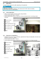
background image

© STULZ GmbH, Hamburg 


                       EN / 10-2015 / 1000683

-

 33 

-

STULZUltraSonic-SystemforDirectRoomHumidificationBNB-


Installation

7. 

Installation

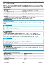
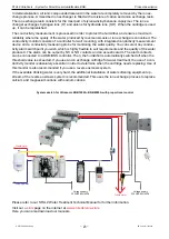
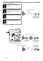
Install the unit in such a way that the mist expelled by the fan is distributed uniformly everywhere in the 

room. Please check that the product package is complete before installation

.

CAUTION

Danger of death. Electric shock risk.

Faultywiringoftheswitchgearcabinetcancausethehumidifiertobecomedefective. 

The 

STULZ 

UltraSonicBNBultrasonichumidifier may only be installed, connected and started up by 

specialist electricians.


Switch gear cabinets must be wired as shown in the wiring diagrams provided.

WARNING

DANGER

CAUTION

Genuine parts.

Use only genuine STULZ parts and genuine spare parts for installation.

CAUTION

Horizontal position.

The unit must be mounted precisely horizontally.


Itisessentialtocheckthepositionofthehumidifierbeforestartingitup!

NOTICE

CAUTION

Upright position.

Do not switch on the master switch under any circumstances if the unit is 

not

 in an upright position.


Itisessentialtocheckthepositionofthehumidifierbeforestartingitup!

NOTICE

CAUTION

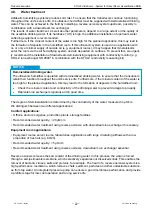
Adhere to set clearances.

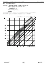
Between the mist guide tube and any component that may be located in front of the unit, leave a clear-

ancethatisgreaterthanthehumidifierdistance.


See section "5.1.Humidifierdistance"onpage27.

NOTICE

CAUTION

Installation clearance.

Leaveminimumclearanceof500mmbetweentheupperedgeoftheultrasonichumidifier 

and the ceiling.


See section "7.2. Installation clearances" on page 36.

NOTICE

CAUTION

Minimum distance between units.

When several units are installed in a room, maintain a minimum distance of 300 mm between them.


See section "7.2. Installation clearances" on page 36.

NOTICE
Summary of Contents for BNB 1000A

Page 1: ...re use Keep for later reference STULZ the natural choice Technical Manual STULZ UltraSonic Humidifier System for direct room humidification BNB BNB 1000A BNB 4000A BNB 2000A BNB 5000A BNB 3000A BNB 80...

Page 2: ...Best regards STULZ GmbH Hotline For general inquiries please get in touch via our hotline on 49 40 5585 252 or hotline stulz de en Technical Support In the event of technical problems please contact o...

Page 3: ...4 5 Technical data 18 4 6 Dimensional drawing 19 4 7 Application limits 20 4 8 Service life of materials 21 4 9 Water treatment 22 4 10 Use in conformity with VDI 6022 24 5 DESIGN AND PLANNING 26 5 1...

Page 4: ...Visual inspection 75 11 4 Cleaning 76 11 4 1 Cleaning water bearing parts 76 1 1 1 Cleaning the air filter 77 11 4 3 Cleaning the water tank transducers and mist guide tubes 78 11 5 Inspect the elect...

Page 5: ...3 Qualification requirements for personnel on page 10 1 3 Conventions regarding illustrations Safety and warning notices are indicated by signal words The signal words indicate hazard levels with a r...

Page 6: ...e microorganisms in a material is determined by culturing L Pipe length in m LED Light emitting diode l h Liters per hour Composite unit for volumetric flowrate m Meter SI base unit Length min Minute...

Page 7: ...ch cases all liability for material defects is excluded 1 9 Copyright All brand and product names are trademarks or registered trademarks of the products bearing these names UltraSonic is a registered...

Page 8: ...TULZ Technical Support 2 1 Proper use The STULZ UltraSonic BNB model series is designed for direct room humidification through the ultra sonic atomization of demineralized drinking water The STULZ Ult...

Page 9: ...er applicable documents are listed in section 2 5 Other applicable documents on page 11 Units must be stationary and switched off before any work is carried out The unit must be discon nected from the...

Page 10: ...ty with the technical documentation All water installation work must be performed exclusively by authorized and trained specialist personnel Specialist personnel within the context of this documentati...

Page 11: ...kaged in a cardboard box Open the box carefully to prevent damage to the unit s surface If the unit is to be placed in interim storage after delivery take the following precautions for protection agai...

Page 12: ...de en e stulz Illustration Description Item BNB 1000 A 8000 A STULZ UltraSonic BNB Quick start Guide Threaded joint for stainless steel tube Connection 6 mm 1 x item 51 2 way main cable BNB 1000 A 40...

Page 13: ...ich in den Wasseranschlussadapter geschraubt Verbindung zur Umkehr Osmose Anlage Zuleitungsventil Anschluss an das Anschluss des vorhandenen Stadtwasser Wasserhahns 25 Abwasser Spannungsversorgung 230...

Page 14: ...cers 72 396 m3 h airfl ow volume Integrated fan Stainless steel housing WNr 1 4301 X5CrNi18 20 WNr 1 4106 X2CrNi19 11 CAUTION Adiabatic behavior STULZ UltraSonic humidifi ers atomize the water in minu...

Page 15: ...ting plate is affi xed to the side of the humidifi er The data on the rating plate are required for the following Safe use of the STULZ UltraSonic BNB ultrasonic humidifi er When phoning the STULZ hot...

Page 16: ...oom Humidification BNB 4 3 Description of unit Units in the UltraSonic BNB model series 1000 A to BNB 8000 A are direct room humidifiers that work on the principle of ultrasonic atomization of deminer...

Page 17: ...gnal of 1 65 MHz The surface of the transducer 1 vibrates at such high speed that the water 2 can no longer follow the movement due to its inertia This produces a column of water 3 above the trans duc...

Page 18: ...USS 503 USM USS 503 USM USS 503 USM USS 1303 USM USS 1303 ON OFF accessory set 1 4 Set 11 Set 5 Set 5 Set 6 Set 7 Set 4 Proportional accessory set 1 5 Set 22 Set 18 Set 18 Set 19 Set 20 Set 17 ON OFF...

Page 19: ...r unit size See 7 5 Electrical connection on page 49 Note Key Item Description Item Description 1 Ultrasonic humidifi er 10 Safety overfl ow 2 Fan housing 11 Mist guide tube 3 Mist guide cover 12 Ring...

Page 20: ...p or during the delivery time of new filter cartridges No longer than 5 of operating hours in total Also see 4 9 Water treatment on page 22 CAUTION Reducing conductivity Depending on the planned appli...

Page 21: ...95 112327 Solenoid Valve with Inlet and Outlet Joint 1 520 SS12S AC48V 2 500 2011 5 1 NS STE010 M67637 L50060 112322 New price valid on and after May 1 2011 loat Switch for with Rubber Packing 480 ow...

Page 22: ...in S cm We distinguish between two different applications Comfort applications Offices doctors surgeries production plants storage facilities Recommended water quality 20 S cm Recommended water treatm...

Page 23: ...suit requirements and the quality of the water produced The alarm can be output by NC or NO contacts and an acoustic alarm The alarm contacts can be connected to a USM USS controller Then the humidifi...

Page 24: ...organic impurities It also stipulates that only materials that do not promote microbial proliferation are used only materials with lasting resistance to corrosion are used all components are easily a...

Page 25: ...il Butadien Styrol Copolymerisat Bevorzugt sollte Edelstahl zum Ein satz kommen Seite 2 von 2 Gesch ftsf hrender Papenreye 61 D 22453 Hamburg Gerichtstand und Sitz der Gesellschafter Telefon 49 40 55...

Page 26: ...ccount of different sizes and boundary conditions 1 Installation conditions Location elevation above sea level Room volume Room air temperature Relative and specific room air humidity Air change rate...

Page 27: ...der Befeuchter nach Bedarf in mehr als 90 der Betriebszeit und verk rzt so die Befeuchterstrecke schont die Schwinger und erh lt die gleichm ige Verteilung des Nebels auch im Teillastbetrieb Die Messu...

Page 28: ...per control on Max The humidifi er distance is reduced in the Min setting See 8 Start up on page 5759 for more extensive informa tion on this setting Against a black background residues of the mist tr...

Page 29: ...nts storage facilities Recommended water quality 20 S cm Recommended water treatment using reverse osmosis with downstream ion exchanger where necessary Reverse osmosis Storage tank Open loop closed l...

Page 30: ...op and closed loop control An external switch gear cabinet is required to operate the UltraSonic humidifier In addition to the trans former required for operation the switch gear cabinet must also hou...

Page 31: ...concepts can subsequently be modified without any major software or hardware changes Control via sensors The microprocessor records humidity and adjusts the ultrasonic humidifiers proportionally By mo...

Page 32: ...ank fill level and connect it to the supplied RC element CAUTION The wrong TVS diodes can cause damage Different TVS diodes can damage the unit Use genuine STULZ spare parts NOTICE CAUTION The wrong c...

Page 33: ...tion The unit must be mounted precisely horizontally It is essential to check the position of the humidifier before starting it up NOTICE CAUTION Upright position Do not switch on the master switch un...

Page 34: ...from frost NOTICE CAUTION Connection elements Only use connection elements of approved materials for installation Also see 4 7 Application limits on page 20 NOTICE CAUTION Fire smoke detectors Do not...

Page 35: ...5 11 10 9 8 7 Item Name 1 UltraSonic BNB 1000 A 8000 A 2 Connector for PE plastic tube 3 Pipe for demineralized drinking water 6 mm 4 Overfl ow pipe 1 2 5 Drainage pipe 1 2 6 Plastic stop cock 7 USM m...

Page 36: ...ons in the fan blow out area must maintain a minimum distance of 5000 mm See section 5 1 Humidifi er distance on page 27 CAUTION Space for maintenance and repair work During installation always leave...

Page 37: ...elevated location If installing the humidifier in an elevated location make sure that it is easily accessible for adjustments inspections maintenance and repair work Insufficient space can cause maint...

Page 38: ...0 550 660 99 Draufsicht Front Ansicht Seitenansicht Hole spacing in mm Unit size BNB 1000 A BNB 2000 A BNB 3000 A BNB 4000 A BNB 5000 A BNB 8000 A Hole spacing 220 330 440 550 660 990 All dimensions i...

Page 39: ...000A 550 200 50 320 4 BNB 3000A 4000A 770 200 50 320 6 BNB 5000A 8000A 1210 200 50 320 8 CAUTION Permitted number of humidifiers No more than one humidifi er may be installed in one safety tray Note M...

Page 40: ...lized drinking water with the conductivity that is suitable for your application see section 4 7 Application limits on page 20 Provide each unit with a stop cock in the drinking water supply pipe Clea...

Page 41: ...amburg EN 10 2015 1000683 41 STULZ UltraSonic System for Direct Room Humidifi cation BNB Installation A B C Connections A Connection for demineralized drinking water B Overfl ow connection C Waste wat...

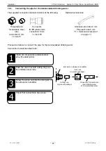
Page 42: ...following Optional accessories 2 Push the union nut with cutting ring over the stainless steel tube 1 Clean all components stainless steel tube threaded joints 3 Screw the union nut onto the inlet joi...

Page 43: ...ter 6 mm stainless steel Cutting ring in product package Union nut Inlet joint in ultrasonic humidifi er Connection for demineral ized drinking water 6 mm PE plastic tube Connector Inlet joint on ultr...

Page 44: ...aminated water pipes Filings and dirt must not get into water pipes All pipes must be cleaned before they are connected to the unit NOTICE CAUTION Position of valves Always install valves below the un...

Page 45: ...g Overfl ow pipe 1 2 provided on site Overfl ow pipe 1 2 provided on site Overfl ow pipe 1 2 provided on site CAUTION Using a safety tray If the humidifi er is mounted on a wall the overfl ow pipe mus...

Page 46: ...Remove the screw plug Valve 48V AC for USM USS 230V AC only for ON OFF control module 3 1 Optional accessories on page 13 Connection to a drainage pipe with solenoid valve is only necessary if the wa...

Page 47: ...Hamburg EN 10 2015 1000683 47 STULZ UltraSonic System for Direct Room Humidifi cation BNB Installation Installation options for the fl ush valve CAUTION Flush valve The bolt and O ring are no longer r...

Page 48: ...nect the other end of the hose to the local waste water system 5 Fasten the drainage hose to the wall us ing suitable materials Make sure there are no kinks or bulges in the hose 6 Make sure that the...

Page 49: ...d the unit and secure so they cannot be switched back on for the duration of the work WARNING DANGER CAUTION Danger of death Electric shock risk Never mount the control cabinet below the humidifi er W...

Page 50: ...R G H H X2 gr n gr n X1 X1 rot rot 1 schwarz H2 rot 4 x 1 25 mm2 2000 mm G1 wei G2 gr n H1 schwarz G1 wei wei G2 gr n gr n H2 rot rot H1 H1 schwarz schwarz Ansicht von L tseite Ansicht von L tseite BN...

Page 51: ...1 1 7 3 5 7 7 LOGO 9 7 5 CM PVU Befeuchter BNB 5000 8000 9 9 USM 1303 Color code black white red green black white red green In circuit diagram bk wh rd gn bk wh rd gn USS 1303 Color code black white...

Page 52: ...eren USS SLAVE Schaltschr nken USS 503 1303 USM master control cabinet USM 503 1303 USS SLAVE control cabinet USM 503 1303 USS SLAVE control cabinet USM 503 1303 Connection cable for ON OFF control mo...

Page 53: ...is 4 or lower the voltage is still within tolerance If the voltage falls below this value however please select a larger cable cross section with the aid of the table Type Electrical supply Current M...

Page 54: ...s possible and extending the supplied cables only in exceptional cases Note CAUTION Limited capacity If the voltage drops by more than 4 the capacity of the unit is limited NOTICE Example A BNB 3000 A...

Page 55: ...rect Room Humidifi cation BNB Installation 7 5 3 Internal wiring BNB 1000 2000 3000 4000 Key CH Relay panel HR Auxiliary relay SV Solenoid valve FS1 Float switch for water supply FS2 Float switch for...

Page 56: ...TULZ UltraSonic System for Direct Room Humidifi cation BNB Key CH Relay panel HR Auxiliary relay SV Solenoid valve FS1 Float switch for water supply FS2 Float switch for low water level TP Thermostat...

Page 57: ...y water in pipes Do not operate the humidifier with stationary water in the pipes NOTICE CAUTION Alignment with airflow Align the humidifier in the direction of the airflow NOTICE CAUTION Water and po...

Page 58: ...ns tight c Is the mist distributed evenly and is there no possibility of condensation 5 If you have made sure the humidifier is function ing correctly start up is complete Otherwise proceed with step...

Page 59: ...guide tubes Adjusting the blow out width and height Completing start up 7 In the event of condensation or larger droplets in the mist the blow out can be adjusted using the setting screw on the side o...

Page 60: ...ter is connected to the supply pipe of all humidifiers All water supply and drainage pipes and the overflow are correctly connected and secured All accessories e g water treatment system sensors fan h...

Page 61: ...during operation a float switch shuts down the ultrasonic humidifier If the water temperature is exceeded the internal temperature monitor is triggered 40 C and switches off the unit CAUTION Automated...

Page 62: ...he parameters of the humidity con troller to achieve the desired air humidity 1 Turn on the tap Proceed as follows to operate the system CAUTION Do not operate without air filters The humidifier must...

Page 63: ...actory setting 1 100 supp Controller gain for supply air controller room Controller gain for room air controller Setpoint menu supp Supply air room Room air suMAX Supply air limitation Proceed as foll...

Page 64: ...nfrd 0 Ausg 0 dr und zus ca 5 s C bet tigen Grundmen dr Befeuchter Me Diagnose Men Curso W T ESC dr cken dr cken T S S W X T ESC OK S W X T ESC OK Programmiermen Stulz Ultrasonic Master Slave Steuerge...

Page 65: ...ity of the supply air is limited to an adjustable maximum value Input 1 External signal 0 10 V Input 2 Supply air sensor 0 1 V Monitoring for sensor fracture Default setting 3 Application 3 The supply...

Page 66: ...est reque 0 outpt 0 mode 1 capacit 1 00 supp 15 00 room 20 00 mode 1 capacit 1 00 supp 15 00 room 20 00 5 Press and hold the OK button until 00001 appears on the mode line 8 Press OK to save the opera...

Page 67: ...s follows to set a setpoint example for operating mode 4 1 Press and hold the Esc button and im mediately afterwards press and hold until setpoint appears on the display 2 You are now in the setpoint...

Page 68: ...2 01234 Diagnose digit Eing nge Befeuchter Ext Anford Anfrd 0 Ausg 0 dr und zus ca 5 s C bet tigen Grundmen dr Befeuchter Me Diagnose Men Curso W T ESC dr cken dr cken T S S W X T ESC OK S W X T ESC...

Page 69: ...ung der Pausezeit 5 Schalter f r Einstellung der Impulszeit 6 Potentiometer f r Einstellung des Impu 2 2 Funktionsdiagramm T Taktzeit tp Pausenzeit ti Impulszeit tw Verz gerungszeit CAUTION Setting th...

Page 70: ...the pulse time 2 Turn the arrow of the potentiometer 6 to position 8 1 Push the DIP switches 5 to the right 2 1 Anzeige und Bedienelemente 1 Gr ne LED Funk 2 Rote LED Relais 3 Potentiometer f r 4 Sch...

Page 71: ...supply and dis charge pipes Drain residual water 2 Turn off the on site tap for the water supply 10 Decommissioning 10 1 Switching off If the humidifier is not going to be used for a longer period ta...

Page 72: ...suitable tools as otherwise damages could be caused NOTICE CAUTION Genuine spare parts Only genuine STULZ spare parts may be used CAUTION Danger of property damage due to electric shock Do not switch...

Page 73: ...nnections for leaks Threaded joints are secure Connectors are secure 6 months Page 74 Transducers Check transducers for deposits 6 months Page 78 Specialist engineer Inspect electrical system Remove c...

Page 74: ...Qualified sampling within the meaning of the Directive refers to sampling for the purpose of risk assessment at the system boundary to the room It must entail expert microbial sampling in accordance...

Page 75: ...ect transducers 5 Assemble the unit in reverse order 3 Remove cover and check inside the unit 2 Check system from the outside Proceed as follows to perform the visual inspection CAUTION Time intervals...

Page 76: ...cting units to the water mains 2 Remove mineral salt residues using commercially available cleaning agents We recommend gentle odorless deter gents based on citric acid 1 Thoroughly clean all water be...

Page 77: ...ing water and allow to dry 5 Next blow out the filter with compressed air 6 Assemble the unit in reverse order 2 Pull out the filter case and filter 1 Slacken the screws on the front of the unit CAUTI...

Page 78: ...e if necessary 2 Slacken the two rear Phillips screws and take off the cover of the water tank 1 Perform steps 1 9 from section 11 5 Inspect the electrical system on page 80 11 4 3 Cleaning the water...

Page 79: ...CAUTION Flush water pipes Flush the water pipes with the highest possible pressure before connecting units to the water mains Note 8 Disinfect the water tank a Brush or spray all parts with 5 hydrogen...

Page 80: ...e water 4 Disconnect water supply and drainage pipes 5 Label electrical supply cables and connections Then disconnect them 6 Drain residual water from the ultrasonic humidifier Put the ultrasonic humi...

Page 81: ...relay PCB or relays for changes in color damage and deposits 15 Check whether electrical cables are damaged and that all cables are rout ed correctly 12 Make sure that the unit has no leaks 9 To remov...

Page 82: ...y PCB into the guide rails 1 Perform steps 1 10 from section 11 5 Inspect the electrical sys tem on page 80 18 Assemble the unit in reverse order 19 Check that all screws are securely tightened CAUTIO...

Page 83: ...3 STULZ UltraSonic System for Direct Room Humidification BNB Maintenance 5 Insert the blade terminal into the new PCB making sure it is correctly assigned 6 Assemble the unit in reverse order 7 Check...

Page 84: ...0 4 Completely remove the panel 5 Slacken the Phillips screw and take the unit out of the housing 6 Rotate the fitting and take out of the unit and remove the fill valve 7 Check the open closed signal...

Page 85: ...ion wir Schalter geschlossen und somit die Stromversorgung des Magnetventi und damit die Wasserversorgung hergestellt ON Status OFF Status OFF Status Magnetring Schalter Der Magnetri Schalter in ge Po...

Page 86: ...on page 80 4 Slacken the two Phillips screws on the cover panel and remove the cover 5 Slacken the two thumb screws of the transducer 6 Detach the supply cable of the transducer and remove the transdu...

Page 87: ...rt a new transducer including new seal and screw tight 8 Reconnect the supply cable and assem ble the unit in reverse order CAUTION Trapped cables During installation take care not to trap any ca bles...

Page 88: ...CB with a genuine spare part from STULZ 5 Reconnect the orange and yellow cables of the transducer and the black and white supply cables and assemble the unit in reverse order 8 9 14 15 9 Item Descrip...

Page 89: ...the Phillips screws and take off the cover of the control system 1 Perform steps 1 10 from section 11 5 Inspect the electrical sys tem on page 80 4 Slacken the four Phillips screws on the lower outer...

Page 90: ...rect disposal may have negative consequences for human health and the environment 4 The symbol affixed to the product packaging and in the instructions for use crossed out waste container on wheels in...

Page 91: ...st guide tube 2 4 6 8 10 16 3 L50070 Nebulizer unit incl silicon sheet not incl housing 2 4 6 8 10 16 4 L50098 Transducer incl cable L 100mm 2 4 6 8 10 16 5 L50095 Nebulizer print plate incl silicon s...

Page 92: ...1 1 1 17 M01416 2 way connector incl cable L 2m 1 1 1 1 18 M01417 4 way connector incl cable L 2m 18a 1 1 18a M75809 90 4 way connector incl cable L 4m 19 M01419 6 way connector incl cable L 2m 1 1 1...

Page 93: ...1 1 1 2 2 3 27 M01319 Air filter 100x10x196 1 28 M01324 Air filter 100x10x306 1 29 M01325 Air filter 100x10x416 1 30 M01326 Air filter 100x10x526 1 31 M01327 Air filter 100x10x636 1 32 M01328 Air filt...

Page 94: ...3000A 4000A 5000A 8000A 34 1220560 Top cover 1 35 1220184 Top cover 1 36 1220561 Top cover electric 1 1 1 1 1 1 37 1220574 Float switch bracket 1 1 1 1 1 1 38 1220575 Mounting feet 1 1 1 1 1 1 39 1220...

Page 95: ...A 4000A 5000A 8000A 45 1220568 Water tank 1 46 1220569 Water tank 1 47 1220570 Water tank 1 48 1220571 Water tank 1 49 1220572 Water tank 1 50 1220573 Water tank 1 51 L50010 Double conical ring and nu...

Page 96: ...6 Exploded view STULZ UltraSonic System for Direct Room Humidification BNB 14 Exploded view 1 2 39 52 38 40 41 42 43 44 26 23 24 25 27 28 29 30 31 32 45 46 47 48 49 50 4 7 8 3 15 5 6 13 51 37 14 9 10...

Page 97: ...opped the unit Water may escape from the overflow A9 Faulty nebulizer unit Check electrical supply H1 G1 If the transducers do not function despite the pow er being on they are faulty Low mist product...

Page 98: ...n of Conformity STULZ UltraSonic System for Direct Room Humidification BNB 16 CE Declaration of Conformity CAUTION Technical documentation to download The technical EC Declaration of Conformity is ava...

Page 99: ...ded view 96 F Fan Fan housing 19 Fill valve 84 Float switch 84 G Genuine spare parts 11 H Hotline II Humidifier capacity 18 Humidifier distance 27 Hygiene 24 I Installation 33 35 36 Installation clear...

Page 100: ...II Switching off 71 T Technical data 18 Technical Support II Troubleshooting 97 TVS diodes 32 U UltraSonic 16 Ultrasonic atomization 17 Ultrasonic humidifier 16 UltraSonic Master 31 UltraSonic Slave 3...

Page 101: ...STULZ GmbH Hamburg EN 10 2015 1000683 101 STULZ UltraSonic System for Direct Room Humidification BNB CE Declaration of Conformity Notes...

Page 102: ...very 6 months Leak test 48 Inspect all screw and push in connections for leaks and a secure fit Every 6 months Clean the air filter 50 Open filter drawer clean filter Every 6 months Clean the water ta...

Page 103: ...STULZ GmbH Hamburg EN 10 2015 1000683 103 STULZ UltraSonic System for Direct Room Humidification BNB Maintenance Checklist Notes...

Page 104: ...pipes and the overflow are correctly connected and secured All accessories e g water treatment system sensors fan have been correctly fitted All pipework channels and shut off valves are known Drinkin...

Page 105: ...STULZ GmbH Hamburg EN 10 2015 1000683 105 STULZ UltraSonic System for Direct Room Humidification BNB Start up Checklist Notes...

Page 106: ...Adequate Poor Electrical test of humidifier Solenoid fill valve OK Damaged tight Comments Oscillators Circuit 1 OK Damaged Comments Oscillators Circuit 2 OK Damaged Comments Fan module OK Damaged Com...

Page 107: ...n rate l h Water treatment intake pressure bar Pressure reducer installed Yes Setting bar Feed water quality Drinking water pipe Well water Demineralized Direct room applications Room volume size m x...

Page 108: ...or circuit diagrams in line with technical developments modifications to the equipment or future market requirements All previous versions of this manual become void upon the publication of this one...

Reviews: