(Mar, 2012)
CeilAiR OHS Series Installation, Operation & Maintenance Manual
Air Technology Systems, Inc.
2.0 Installation
2.1 Receiving the Equipment
Your
CeilAiR
OHS system has been tested
and inspected prior to shipment. To ensure that
your equipment has been received in excellent
condition, make a visual inspection of the equipment
immediately upon delivery. Carefully remove the
shipping container and all protective packaging.
Remove the access panels and thoroughly inspect
the unit interior for any signs of transit-incurred
damage. If there is shipping damage, it must be
noted on the freight carrier’s delivery forms BEFORE
signing for the equipment. Any freight claims MUST
be done through the freight carrier. SATS ships all
equipment FOB. SATS can assist in the claim fi ling
process with the freight carrier. Should any damage
be present, notify the SATS Product Support Group
prior to attempting any repairs. Refer to section fi ve
of this manual for instructions.
A unit Data Package has been sent with your unit. It
contains this manual, system drawings, applicable
MSDS’s, other component manuals and any other
applicable instructions based on the confi guration
and options of your unit. The data package has been
affi xed to your unit in a clear plastic bag. These docu-
ments need to be kept with the unit for future service.
NOTE
Items that have been shipped loose such as
controllers, humidistats, vibration isolators,
buck/boost transformers, etc. are shipped
inside the air conditioner unless specified
otherwise by the customer. Grilles (if applicable)
are placed on top of the air conditioner inside
the unit’s carton. Remove and store these items
in a safe place unless you are using them im-
mediately.
2.2 Site Preparation
CeilAiR
systems are designed with easy service
access in mind. Component access panels are
located on the front and rear sides of the equipment.
Additional access to some components may be
obtained through the bottom of the unit on spot
cooler confi gurations. These units can be fully
serviced in the ceiling plenum. In order to have full
service access, the air conditioner must be located
so that adequate space is provided in front of all
access panels.
NOTE
Working clearance requirements need to be
established prior to the mounting of the unit.
Refer to local and national electrical codes.
To minimize the effects of the environment
surrounding the conditioned space, certain steps
must be taken. This is especially true for critical/
precision room preparation (computer rooms/labs)
requiring close tolerance control of temperature
and humidity. The conditioned space should be well
insulated and include a vapor barrier. The installer
should ensure that the proper insulation rating is
used based on the design of the space, which was the
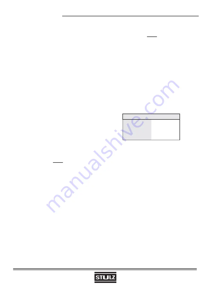
basis for the system selected. The following chart is a
recommended minimum R-value (thermal resistance) to
ensure optimum equipment operation.
The vapor barrier is the single most important
requirement for maintaining environmental control
in the conditioned space. The vapor barrier in
the ceiling and walls can be polyethylene fi lm.
Concrete walls and fl oors should be painted with a
rubber or plastic-based paint. Doors and windows
should be properly sealed and a door sweep used
to minimize leakage. Outside or fresh air should
be kept to a minimum (as it adds to the cooling,
heating, dehumidifi cation and humidifying loads),
while maintaining the requirement of the Indoor Air
Quality (IAQ) Standard. Lack of these steps can
cause erratic operation, unstable room control and
excessive maintenance costs.
2.3 Rigging
CeilAiR
systems are designed to be kept in a
horizontal position. The unit is shipped on a skid to
facilitate moving prior to installation. A suitable lifting
device should be used to lift the unit from the bottom.
A weight table is provided for reference on the
installation drawing. The unit should always be stored
indoors in a dry location prior to installation.
STRUCTURE R-VALUE
Ceiling
R-38
Wall
R-21
Floor
R-19
Door
R-5
2-1


