(Mar, 2012)
CeilAiR OHS Series Installation, Operation & Maintenance Manual
Air Technology Systems, Inc.
2-6
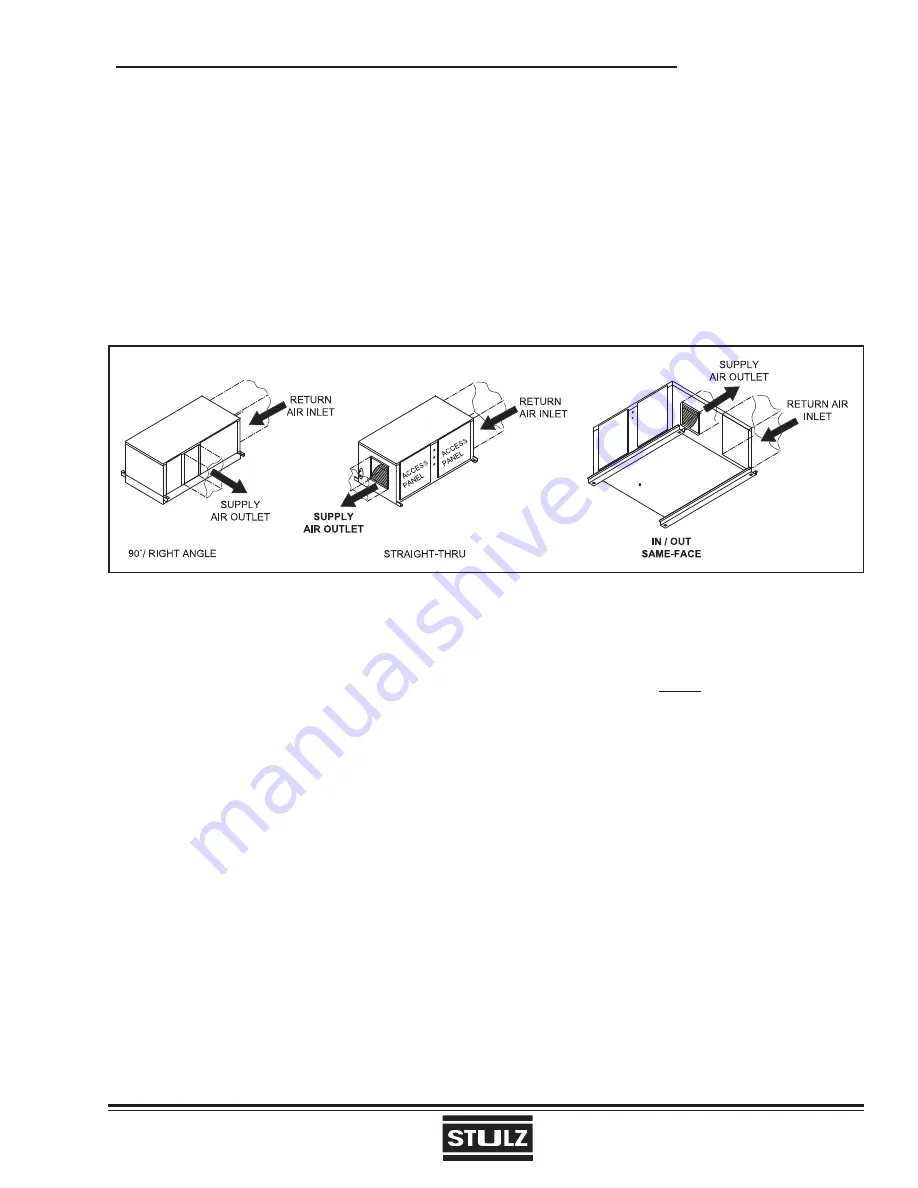
2.5.2 Ducted Systems (See Figure 3)
There are three basic confi gurations of airfl ow patterns: 90º/Right Angle, Straight-Thru and In/Out Same-Face.
When determining ducting requirements, always consult your local and state codes. The duct system should be
designed to allow the air to move with as little resistance as possible. Several factors determine ducting material
and size. These factors are predetermined, refer to your ducting system schematic.
The connection of ducting to the unit is typically accomplished with a one-inch duct fl ange. Supply air outlet and
return air inlet ducts will require a fi eld provided duct fl ange (refer to the installation drawing provided with the
unit). The connection of ductwork to the unit may be made with either pop rivets or self-tapping screws.
2.6 Piping Connections
2.6.1 Refrigerant
2.6.1.1 Self-Contained Systems
No refrigeration connections are required for self-
contained air, water or glycol-cooled systems (Mod-
els OHS-012/040-AS, OHS-012/120-C and OHS-
012/120-W/G-( )).
2.6.1.2 Split Systems
Split air-cooled systems will require fi eld refrigera-
tion piping. All split systems are shipped with a dry
nitrogen charge of 100 psig.
2.6.1.2.1 Remote Air Cooled Condensers
(AR
Models)
Systems utilizing a remote condenser will require a
copper liquid line and discharge line. The piping must
not have a refrigerant line pressure drop over 14 psig
across the condenser and the interconnecting piping
to the condenser sections.
If the condenser is installed above the evaporator,
the discharge line should include a P-trap at the
evaporator.
Figure 3- Ducted System Typical Air Patterns
NOTE
Ensure proper condenser selection to maintain
reasonable sub-cooling temperatures.
If the condenser is installed below the evaporator,
an inverted trap the height of the evaporator coil is
required on the liquid line to help prevent oil and liquid
from fl ooding back to the compressor during off cycles.
Refer to the Recommended Discharge Line and Rec-
ommended Liquid Line sizing tables on page 2-7.
All refrigeration piping should be installed with high
temperature brazed joints. Use standard refrigeration
practices for piping supports, leak testing, dehydra-
tion and charging of the refrigeration circuits. The
refrigeration piping should be isolated from the build-
ing by the use of vibration isolating supports. Provide
supports (clamps or hangers) as necessary every 5
to 10 feet along piping runs to minimize vibration and
noise transmission. To prevent tube damage when
sealing openings in walls and to reduce vibration
transmission, use a soft fl exible material to pack
around the tubes.


