32
1
2
EN/06.2021/G23 © STULZ GmbH – all rights reserved
minispace cw original instructions
5.5 electrical connection
The power supply system on site and the pre-fuse must be designed for the total current of the unit (see e-da-
ta sheet).
Make sure that the power supply corresponds to the indications on the rating plate and that the tolerances
according to the „Application limits“ are not exceeded.
The asymmetry of phase between the conductors may amount to 2% maximally.
To determine the asymmetry of phase measure the voltage difference between the phase conductors
(L1-L2,
L2-L3, L1-L3) and calculate the average value of the measured voltages. With a voltage supply of 400V, the
maximum deviation to the average value of the voltages may not exceed 8 V.
DAnGer
Mortal danger by electric hazard
Ensure that the power supply at the connection cable is de-energized.
The electric cables are only to be connected by an authorized specialist.
noTICe
Make sure that the phase rotation is correct, the rotating field must turn right! Otherwise a three
phase control device (optional) triggers an alarm.
noTICe
For use of leakage-current (FI) circuit breakers, take into account the EN 50178 5.2.11.2 .
Only type B pulse-current FI circuit breakers are permitted. FI circuit breakers do not provide
protection against bodily harm during operation of the unit or frequency converters.
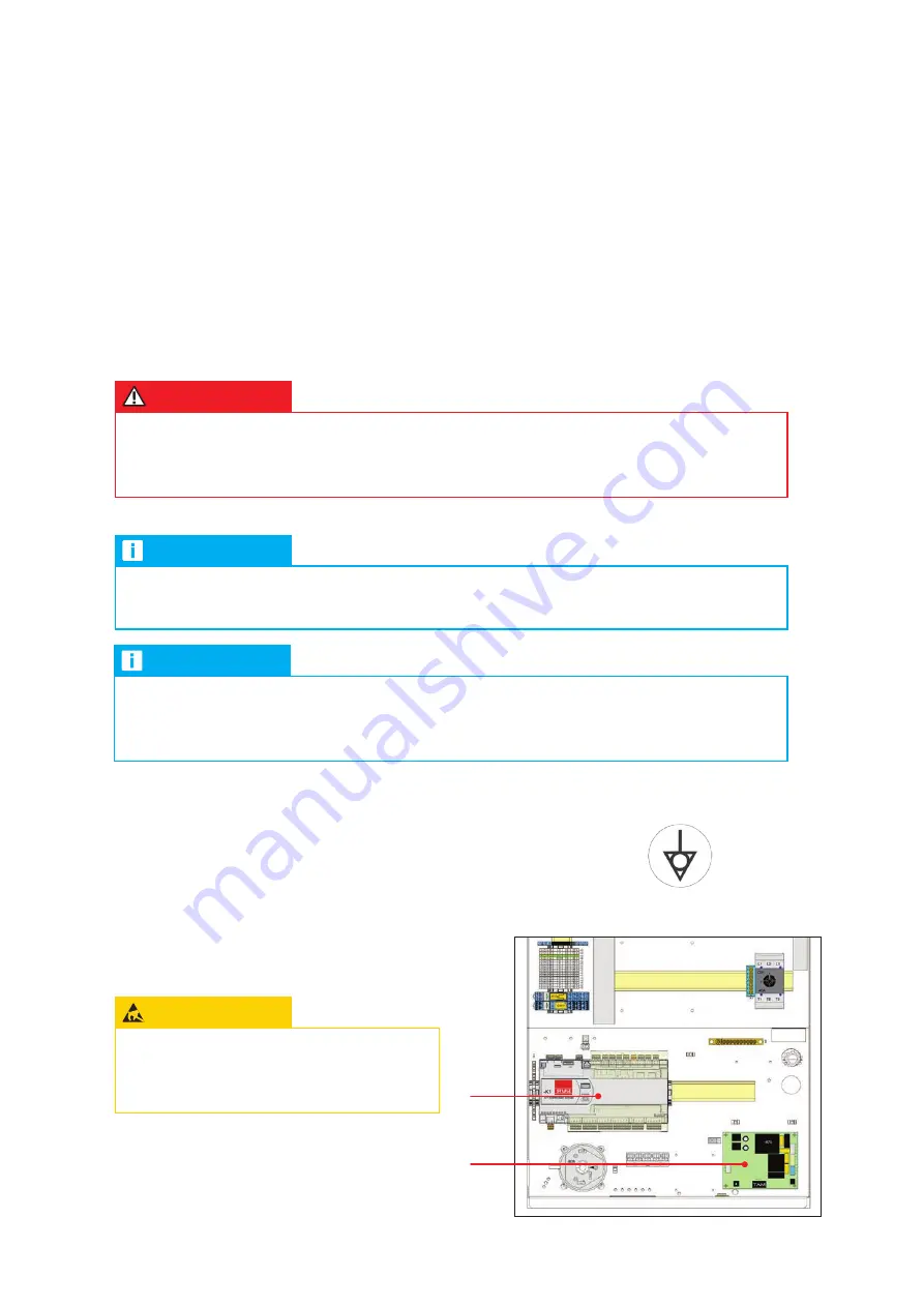
eSD noTe
Do not touch electronical components,
without taking care of protective ESD
measures.
• open the unit door, on which the main switch is located.
• establish an effective equipotential bonding to the unit frame.
The connection bolt provided for this purpose is marked with this symbol:
Electronical components:
- Controller (1)
- Humidifier board (option) (2)
• check that the feedthrough openings in the unit
are provided with rubber grommets. If the rubber
grommets are lacking, the cable insulation can be
damaged.

