39
Cyberair mini Cw original instruCtions
© STULZ GmbH – all rights reserved EN/06.2021/G23
Heat exchanger
The heat exchanger consists of copper tubes with aluminium fins. If leaks occur, they should be searched for
at the heat exchanger. Beyond that, the heat exchanger is exposed to the air pollution, the particles of which
settle at the fins and reduce the heat transmission the same as raise the air resistance.
notiCe
Do not distort the fins while cleaning, this also increases the air resistance.
• clean the heat exchanger by pressurized air by blowing it opposite to the normal air flow direction along the
fins.
7.3 Air circuit
Air filter
A filter monitor controls the state of the filter. As soon as the pressure
loss exceeds an adjustable value, a filter alarm via the controller is
released. The controller can be configured such as to compensate the
pressure loss by a higher fan speed, however you should not wait too
long for exchanging the filter.
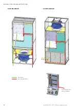
In upflow units the filters can be accessed by the lower front panel. In
downflow units, the filters can be pulled out to the front after opening
the front door. If there is a second filter element (for sizes 2-4), this can
only be pulled out after the first element has been removed.
The clogged filter elements can not be cleaned with pressurized air, as
the filter structure would be destroyed otherwise.
When you re-install the filter elements after the exchange, take care
that the side with the coloured mark (dirt side) is turned away from the
heat exchanger.
Filter position in upflow unit
Filter position in downflow unit
CAUtion
Risk of injury from sharp edges
The fins of the heat exchanger and the condensate drip tray are sharp-edged. Wear safety
gloves and cover forearms.


