background image

40

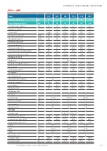
M4 M3  M2  M1

M8 M4

Modell

M1

M2

M3

M4

M5

M6

M7

M8

CSO 1102 ASN

kg

139

254

233

135

148

280

256

148

CSO 1302 ASN

kg

146

269

248

146

150

282

260

150

CSO 1102 ASF

kg

148

267

245

146

209

389

356

209

CSO 1302 ASF

kg

155

276

253

154

215

399

366

216

CQO 802 ASN

kg

121

213

229

115

140

270

246

143

CQO 1102 ASN

kg

140

256

235

136

149

282

258

149

CQO 802 ASF

kg

135

246

229

124

199

380

348

210

CQO 1102 ASF

kg

150

270

248

148

211

393

360

211

 EN/09.2019/G42  © STULZ GmbH – all rights reserved

cybercool 2 scroll original insTrUcTions

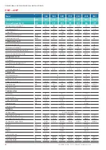
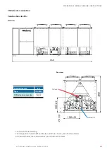
Construction size 4

Bottom view

right

left

front

Air inlet zone

The weights are indicated with a tolerance of ±5%.

Model

Summary of Contents for CyberCool 2 CQO 1102 ASF

Page 1: ...CyberCool 2 Original instructions Precision Chillers Scroll compressor 400V 50Hz 3Ph N PE Index G42 Issue 9 2019 ...

Page 2: ...ing technology business spe cialising in A C for data centres and telecommunications installations STULZ has ten production plants 2 in Germany Italy the USA Great Britain Spain 2 in China Brazil and India and twenty subsidiaries in Germany France Italy Great Britain Belgium Brazil the Netherlands New Zealand Mexico Austria Poland Spain Singapore China India Indonesia South Africa Sweden Australia...

Page 3: ...lerfrom STULZ The units which were produced in Hamburg have been developed especiallyfor use in Data Cen ters and industry and satisfy all requirements for efficiency and reliability For general inquiries our hotline is available at 49 40 5585 5000 Our service hours are weekdays from 7am 4pm Forfurther information concerning our products and services visit ourwebsite www stulz com ...

Page 4: ...4 4 EN 09 2019 G42 STULZ GmbH all rights reserved CYBERCOOL 2 SCROLL ORIGINAL INSTRUCTIONS ...

Page 5: ...sitioning 37 5 2 Weights on the supports 39 5 3 External water circuit 45 5 4 Electrical connection 51 6 Commissioning 56 6 1 Filling ofthe water circuit 56 6 2 Control ofthe electrical box 58 6 3 Oil pre heating 62 6 4 Commissioning ofthe chilled water circuit 62 6 5 Commissioning ofthe refrigerant circuits 63 7 Maintenance 65 7 1 Safety instructions 65 7 2 Maintenance intervals 65 7 3 Refrigeran...

Page 6: ...ently available at the place where the system is used danger Works have to be carried out by competent staff only Safety devices may not be bypassed 1 3 Handling refrigerants Get qualified refrigeration technicians to carry out the work Wear safety glasses and safety gloves Liquid refrigerant must not get onto the skin risk of burns Do not inhale refrigerant vapours Refrigerants have a narcotic ef...

Page 7: ...t protocol must be kept b To be stored in the proximity ofthe unit c Access for competent staff in case of repairs and repeated inspection must be ensured Repeated inspection according to EN 378 The operator is responsible forthe execution The operator must ensure that all maintenance inspection and assemblywork is carried out by authorised and qualified specialist staffwho have made an in depth s...

Page 8: ...ations must be checked country specifically notice When delivery is accepted check the unit against the consignment papers for completeness and for external damage and record it on the consignment papers in the presence ofthe freight forwarder You receive the consignment papers with the delivery ofthe chiller unit The shipment is made ex works in case of shipment damages please assert your claim t...

Page 9: ... 4 Forthe transport there are openings in the base frame through which steel tubes must be pushed The steel tubes are not delivered and must be provided bythe customer Requirements for the steel tubes Length minimum 1600 mm Diameter 50 mm according to unit net weight Wall thickness according to unit net weight To prevent the ropes from sliding offthe steel tubes fasten a clamp at the end ofthe tub...

Page 10: ...21 ASF 999 627 1079 EN 09 2019 G42 STULZ GmbH all rights reserved cybercool 2 scroll original INSTRUCTIONS G unit transport weight S centre of gravity Construction size 3 The co ordinates ofthe centre of gravity are indicated with a tolerance of 50 mm notice Consider also the weight of the cross beam when you order the crane The rope forces are higherthan the weight forces according to the geometr...

Page 11: ...0 650 1442 CQO 1102 ASN 1702 630 1565 CQO 802 ASF 1730 760 1722 CQO 1102 ASF 1785 736 1849 STULZ GmbH all rights reserved EN 09 2019 G42 cybercool 2 scroll original INSTRUCTIONS G unit transport weight S centre of gravity Construction size 4 The ropes or belts named byA B C and D must have the same length The co ordinates ofthe centre of gravity are indicated with a tolerance of 50 mm Model ...

Page 12: ...device must consist oftwo cross beams The drawings on the following pages showthe dimensions forthe suspension points and the position ofthe centre of gravity Suspension at the lifting lugs After installation remove the lifting lugs and keep them for future transport notice Consider also the weight of the cross beams when you order the crane The rope forces are higherthan the weight forces accordi...

Page 13: ...CQO 1302 ASN 1680 2808 CQO 1602 ASN 1710 3112 CQO 1902 ASN 1720 3154 CQO 1302 ASF 1920 3247 CQO 1602 ASF 1860 3555 CQO 1902 ASF 1860 3597 STULZ GmbH all rights reserved EN 09 2019 G42 cybercool 2 scroll original INSTRUCTIONS Construction size 5 The co ordinates ofthe centre of gravity are indicated with a tolerance of 50 mm Model G unit transport weight S centre of gravity The ropes or belts named...

Page 14: ... CQO 2402 ASN 2180 3713 CQO 2802 ASN 2200 3779 CQO 3702 ASN 1880 4319 CQO 2402 ASF 2290 4295 CQO 2802 ASF 2300 4366 CQO 3702 ASF 2000 4907 EN 09 2019 G42 STULZ GmbH all rights reserved cybercool 2 scroll original INSTRUCTIONS Construction size 6 The co ordinates ofthe centre of gravity are indicated with a tolerance of 50 mm Model G unit transport weight S centre of gravity The ropes or belts name...

Page 15: ... CSO 4202 ASF 2660 5374 STULZ GmbH all rights reserved EN 09 2019 G42 cybercool 2 scroll original INSTRUCTIONS Construction size 6 The co ordinates ofthe centre of gravity are indicated with a tolerance of 50 mm Model G unit transport weight S centre of gravity The ropes or belts named byA B C and D must have the same length ...

Page 16: ... CQO 4002 ASN 2790 5035 CQO 4602 ASN 2630 5558 CQO 5002 ASN 2830 5234 CQO 4002 ASF 3095 6017 CQO 4602 ASF 2950 6542 CQO 5002 ASF 3130 6207 EN 09 2019 G42 STULZ GmbH all rights reserved cybercool 2 scroll original INSTRUCTIONS Construction size 7 The co ordinates ofthe centre of gravity are indicated with a tolerance of 50 mm Model G unit transport weight S centre of gravity The ropes or belts name...

Page 17: ...protection grille the protection grilles must be unscrewed to remove the polypropylene plates Remove these plates before start up Coil protection grille optional housing protection grille optional Option Coil protection grille The spacers are enclosed in the electrical cabinet Unscrewthe coil protection grille 6 screws Remove the transport protection plates Place the spacers 4 pieces each on the p...

Page 18: ...n max BP 14 bar Temperatur min max Temperature min max Température min max 10 100 C R410A 0098 C S O 280 2 A S N EN 09 2019 G42 STULZ GmbH all rights reserved cybercool 2 scroll original INSTRUCTIONS Free cooling N without free cooling F with free cooling glycol Outdoor temperature range S standard Condenser cooling version A air cooled Number of refrigerant circuits 1 2 No Nominal cooling capacit...

Page 19: ... is designed for outdoor installation Any use beyond this is not deemed to be use as intended STULZ is not liable for any damage resulting from such misuse The operator alone bears the risk The chillers ofthe CyberCool2 series with scoll compressors exist in 5 construction sizes which differ bytheir dimensions design and cooling capacity An overview ofthe construction sizes 3 to 7 can be seen on p...

Page 20: ...on CSO CQO _ _ _ _ ASF This version additionally contains a free cooling coil for each refrigerant circuit The free cooling coils are con nected in parallel in the water side circuit During free cooling mode two motor driven 2 wayvalves size 3 and 4 one 3 wayvalve direct the watervolume flow completelythrough the free cooling coils before it flows through the evaporator Iffree cooling is not possi...

Page 21: ...e compressor contains a crankcase heater Electric cabinet The electric cabinet is divided into a load section and a control section with separate door The load section contains a power switch operable from outside which locks the cabinet doorwhen switched on Athermostatically controlled air water heat exchangerfor cooling at high ambient temperatures is situated inside the electric cabinet on the ...

Page 22: ...ction gas pressure evaporation pressure Chilled water circuit chilled water inlet temperature chilled water outlet temperature flow sensor frost protection thermostat intermediate temperature free cooling In units with free cooling exists an additional sensorforthe chilled watertemperature which is measured at the free cool ing coil outlet Airtemperatures electric cabinet inside temperature compre...

Page 23: ...he electric network or UPS system must be grounded neutral wye the voltage distortions must be within the limits stated below and no inadmissibly high DC voltage portions may exist transient peak over voltage phase to ground max 4 kV 1 2 50µs wave form Z 12 Ohms in acc to ANSI transient peak over voltage phase to phase max 2 kV 1 2 50µs wave form Z 2 Ohms in acc to ANSI ripple voltage phase to gro...

Page 24: ... Wasservolumenstom c m h 5 8 6 6 8 3 11 5 14 2 17 5 Modellreihe CQO ASN 1 1902 2402 2802 3702 4002 4602 5002 Max Außentemperatur a C 45 5 47 4 45 8 42 5 47 4 45 9 44 9 max Wasservolumenstom b m h 42 4 55 1 63 1 77 7 91 7 103 3 111 5 min Wasservolumenstom c m h 20 26 29 8 36 7 43 2 48 7 52 7 EN 09 2019 G42 STULZ GmbH all rights reserved cybercool 2 scroll original INSTRUCTIONS 1 Water without free ...

Page 25: ...ature a C max watervolume flow b m h min watervolume flow c m h Chilled water quality notice Observe the following limits forthe water circuit ofthe chiller Water properties and ingredients Carbonate hardness dH 4 Carbonate hardness when adding inhibitors dH 20 Total hardness dH 15 pH value 7 0 9 0 pH value with light metal 7 0 7 5 Chloride content mg l 100 Chloride content with austenitic steels ...

Page 26: ... Sound pressure level full load in 1m distance underfree field conditions according to ISO 3744 3 Sound power level full load underfree field conditions according to ISO 3744 4 Water inlet temperature 18 C glycol content 30 outdoortemperature 6 C Transport weight net weight weight of refrigerant charge Operating weight transport weight weight ofwater content notice The data are for chiller units i...

Page 27: ...1 7 3 4 8 4 Nennstrom A 2 9 5 6 12 8 Gerätedaten Spannungsversorgung 400V 50Hz 3Ph N PE Betriebsstrom OA 1 A 26 1 29 4 38 2 52 1 58 8 80 7 90 5 maximaler Betriebsstrom RLA A 32 3 36 8 45 2 63 6 72 7 99 3 112 9 Kurzschlussstrom LRA A 125 1 133 8 160 2 151 2 163 1 179 8 195 Länge mm 2300 4200 3950 Breite mm 1300 1300 2300 Höhe mm 2350 2350 2510 Baugröße 3 4 5 Transportgewicht kg 915 926 948 1550 160...

Page 28: ...stung kW 8 4 12 6 15 4 21 Nennstrom A 12 8 19 2 25 6 32 Gerätedaten Spannungsversorgung 400V 50Hz 3Ph N PE Betriebsstrom OA 1 A 116 8 146 3 178 0 191 188 4 219 9 236 9 283 5 maximaler Betriebsstrom RLA A 138 176 5 208 4 221 2 240 6 265 9 285 4 334 4 Kurzschlussstrom LRA A 238 9 298 2 375 7 456 7 463 8 459 1 591 4 550 1 Länge mm 3950 5030 6170 7250 Breite mm 2300 2300 2300 2300 Höhe mm 2510 2510 25...

Page 29: ... 4 3 8 Nennleistung kW 1 9 7 4 11 5 Nennstrom A 2 9 11 4 17 6 Gerätedaten Spannungsversorgung 400V 50Hz 3Ph N PE Betriebsstrom OA 1 A 27 1 30 5 39 3 54 3 60 9 83 7 93 5 maximaler Betriebsstrom RLA A 35 2 39 7 48 1 69 4 78 5 104 1 117 7 Kurzschlussstrom LRA A 126 2 134 8 161 3 153 3 165 3 182 8 197 9 Länge mm 2300 4200 3950 Breite mm 1300 1300 2300 Höhe mm 2350 2350 2510 Baugröße 3 4 5 Transportgew...

Page 30: ...tung kW 8 11 9 15 9 19 9 Nennleistung kW 11 5 17 3 23 28 8 Nennstrom A 17 6 26 4 35 2 44 Gerätedaten Spannungsversorgung 400V 50Hz 3Ph N PE Betriebsstrom OA 1 A 119 7 150 7 182 5 195 5 193 3 227 3 244 3 290 9 maximaler Betriebsstrom RLA A 142 8 183 7 215 6 228 4 250 2 277 9 297 4 346 4 Kurzschlussstrom LRA A 241 8 302 6 380 1 461 2 469 8 466 5 598 8 557 5 Länge mm 3950 5030 6170 7250 Breite mm 230...

Page 31: ...aten Spannungsversorgung 400V 50Hz 3Ph N PE Betriebsstrom OA 1 A 25 9 29 9 34 2 51 8 56 3 77 3 maximaler Betriebsstrom RLA A 32 3 36 8 47 5 63 6 79 9 99 3 Kurzschlussstrom LRA A 124 5 133 5 101 1 150 4 161 1 176 Länge mm 2300 4200 3950 Breite mm 1300 1300 2300 Höhe mm 2350 2350 2510 Baugröße 3 4 5 Transportgewicht kg 924 935 1442 1565 2808 3112 Betriebsgewicht kg 991 1004 1474 1605 2862 3169 CQO A...

Page 32: ...nnstrom A 12 8 19 2 32 Gerätedaten Spannungsversorgung 400V 50Hz 3Ph N PE Betriebsstrom OA 1 A 88 8 109 1 142 8 178 7 177 3 213 3 232 5 maximaler Betriebsstrom RLA A 112 9 144 4 176 5 208 4 234 265 9 285 4 Kurzschlussstrom LRA A 192 6 231 8 293 9 374 8 445 2 451 2 584 6 Länge mm 3950 5030 7250 Breite mm 2300 2300 2300 Höhe mm 2510 2510 2510 Baugröße 5 6 7 Transportgewicht kg 3154 3713 3779 4319 50...

Page 33: ...rom A 5 7 11 4 17 6 Gerätedaten Spannungsversorgung 400V 50Hz 3Ph N PE Betriebsstrom OA 1 A 25 9 29 9 34 2 51 8 56 3 77 3 maximaler Betriebsstrom RLA A 32 3 36 8 47 5 63 6 79 9 99 3 Kurzschlussstrom LRA A 124 5 133 5 101 1 150 4 161 1 176 Länge mm 2300 4200 3950 Breite mm 1300 1300 2300 Höhe mm 2350 2350 2510 Baugröße 3 4 5 Transportgewicht kg 1068 1079 1722 1849 3247 3555 Betriebsgewicht kg 1135 ...

Page 34: ...eistung kW 11 5 17 3 28 8 Nennstrom A 17 6 26 4 44 Gerätedaten Spannungsversorgung 400V 50Hz 3Ph N PE Betriebsstrom OA 1 A 88 8 109 1 142 8 178 7 177 3 213 3 232 5 maximaler Betriebsstrom RLA A 112 9 144 4 176 5 208 4 234 265 9 285 4 Kurzschlussstrom LRA A 192 6 231 8 293 9 374 8 445 2 451 2 584 6 Länge mm 3950 5030 7250 Breite mm 2300 2300 2300 Höhe mm 2510 2510 2510 Baugröße 5 6 7 Transportgewic...

Page 35: ...300 1300 2350 1300 2350 3950 2300 2510 STULZ GmbH all rights reserved EN 09 2019 G42 cybercool 2 scroll original INSTRUCTIONS 4 3 Dimensional drawings Construction size 3 Construction size 4 Construction size 5 ...

Page 36: ...36 5030 7250 6170 2300 2510 2300 2510 2300 2510 EN 09 2019 G42 STULZ GmbH all rights reserved cybercool 2 scroll original INSTRUCTIONS Construction size 6 Construction size 7 Construction size 6 ...

Page 37: ...by aerodynamically disadvantageous conditions 5 Installation 5 1 Positioning The fins ofthe air cooled free cooling coils are made of a high quality aluminum alloy Depending on the site an extended protection against corrosion may be necessary In the vicinity of industrial plants orwaste incinerators elevated levels of carbon dioxide carbon monoxide ammonia nitrogen oxides hydrocarbons sulphur com...

Page 38: ... original INSTRUCTIONS Maintenance clearance Space needed for individual installation and multiple unit installation Take into account the necessary clearances forthe maintenance and the airflow Keep a clearance of 1 m around the unit to every side Above the fans a clearance of 2 5 m is required ...

Page 39: ...6 173 CSO 801 ASF kg 228 178 134 233 214 181 CQO 541 ASN kg 222 170 120 195 158 126 CQO 621 ASN kg 222 173 123 198 160 128 CQO 541 ASF kg 226 175 127 228 205 173 CQO 621 ASF kg 230 177 129 229 208 175 STULZ GmbH all rights reserved EN 09 2019 G42 cybercool 2 scroll original INSTRUCTIONS 5 2 Weights on the supports Construction size 3 Bottom view right left front Air inlet zone The weights are indi...

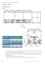
Page 40: ...6 253 154 215 399 366 216 CQO 802 ASN kg 121 213 229 115 140 270 246 143 CQO 1102 ASN kg 140 256 235 136 149 282 258 149 CQO 802 ASF kg 135 246 229 124 199 380 348 210 CQO 1102 ASF kg 150 270 248 148 211 393 360 211 EN 09 2019 G42 STULZ GmbH all rights reserved cybercool 2 scroll original INSTRUCTIONS Construction size 4 Bottom view right left front Air inlet zone The weights are indicated with a ...

Page 41: ...CQO 1302 ASN kg 385 460 390 196 CQO 1602 ASN kg 431 515 429 208 CQO 1902 ASN kg 436 525 440 214 CQO 1302 ASF kg 409 526 488 281 CQO 1602 ASF kg 451 588 535 289 CQO 1902 ASF kg 455 598 546 294 STULZ GmbH all rights reserved EN 09 2019 G42 cybercool 2 scroll original INSTRUCTIONS Construction size 5 The weight on the support Mxr M1 M2 M3 M4 is equal to the weight on the support Mxl The weights are i...

Page 42: ...CQO 2402 ASN kg 445 587 627 239 CQO 2802 ASN kg 454 601 647 249 CQO 3702 ASN kg 533 732 734 244 CQO 2402 ASF kg 462 686 814 324 CQO 2802 ASF kg 464 703 842 320 CQO 3702 ASF kg 538 834 934 314 EN 09 2019 G42 STULZ GmbH all rights reserved cybercool 2 scroll original INSTRUCTIONS Construction size 6 The weight on the support Mxr M1 M2 M3 M4 is equal to the weight on the support Mxl The weights are i...

Page 43: ...24 CSO 4202 ASF kg 470 713 748 639 323 STULZ GmbH all rights reserved EN 09 2019 G42 cybercool 2 scroll original INSTRUCTIONS Construction size 6 The weight on the support Mxr M1 M2 M3 M5 is equal to the weight on the support Mxl The weights are indicated with a tolerance of 5 Model ...

Page 44: ...50 CQO 4002 ASN kg 499 599 570 640 296 CQO 4602 ASN kg 554 676 637 720 322 CQO 5002 ASN kg 504 607 600 714 323 CQO 4002 ASF kg 522 685 752 890 424 CQO 4602 ASF kg 555 752 818 980 434 CQO 5002 ASF kg 510 683 779 970 432 EN 09 2019 G42 STULZ GmbH all rights reserved cybercool 2 scroll original INSTRUCTIONS Construction size 7 The weights are indicated with a tolerance of 5 Model The weight on the su...

Page 45: ...ded ifthe watervolume ofthe water circuit is less than 10 litres kW cooling capacity The storage tank should be lined out with thermical insulation expansion tank with safetyvalve to ensure a possibility of expansion forthe liquid at temperature variations The expansion tank must be dimensioned in such a waythat the water circuit volume can increase by 2 without draining off liquid through the saf...

Page 46: ...n option Outside temperature sensor Free cooling valves only forversions ASF AHF of construction sizes 5 7 Longer storage and standstill periods more than 1 month lead to the bonding ofthe valve flaps The free cooling valves are located in the vicinity ofthe compressor cabinet centered belowthe air heat exchang ers An access is possible via the rear side ofthe chiller Move both free cooling valves...

Page 47: ...struction size 3 Water outlet Water inlet Construction size 4 Size 3 4 Rearview Construction size 3 4 Chilled water connection G1 1 2 internal thread G2 1 2 internal thread Chilled water connection notice Ifthe unit is equipped with the option pump the connection dimensions change Ask for a separate drawing ...

Page 48: ...5 Construction size 6 Water inlet Water outlet Side view Rearview Construction size 5 6 Type CSO CSO 2802 CSO 3702 CSO 4002 Chilled water connection G2 1 2 internal thread DN 80 flange DN 80 flange DN 80 flange Construction size 5 6 Type CQO CQO 2402 CQO 2802 CQO 3702 Chilled water connection G2 1 2 internal thread G2 1 2 int thread DN 80 flange DN 80 flange Side view Rearview ...

Page 49: ...tlet Rearview Chilled water connection Construction size 6 Side view Construction size 6 Type CSO 4202 Chilled water connection DN 100 flange To avoid misunderstanding The designation water inlet and water outlet are chosen seen from the chiller At the water outlet the chilled water is provided from the chiller ...

Page 50: ...ifthey get in contact with external air to prevent the introduction of heat from the ambient air as well as possible Remove the protective hoods from the water pipes Connect the external piping to the chilled water lines ofthe chillerfree of mechanical stress Rearview Water inlet Water outlet Chilled water connection Construction size 7 Side view Construction size 7 Type CSO 4602 CSO 5002 CSO 5902...

Page 51: ... maximum deviation to the average value ofthe voltages may not exceed 8 V danger Mortal danger by electric hazard Ensure that the power supply at the connection cable is de energized The electric cables are onlyto be connected by an authorized specialist notice Make sure that the phase rotation is correct the rotating field must turn right Otherwise a three phase control device optional triggers a...

Page 52: ...handle The door locking mechanism will be released in doing so 4 The second door ofthe power section can be opened byturning the inner locking lever counterclockwise Electric cabinet key Connection of the power supply cable route the power supply cable in the unit as shown in the following illustrations and fix it at the unit frame route the electric cable into the electrical box from below and co...

Page 53: ...he electric cabinet from the bottom The following bottom views displaythe apertures Size 3 Size 4 Air inlet Air inlet Reserve Option second power supply Power supply Grounding Condensate drain of el cabi net Outside temp sensor Control line Reserve Condensate drain of el cabinet cooling Grounding Control line Option second power supply Power supply Outside temp sensor ...

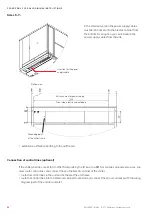
Page 54: ...rs Entrance area for power supply Connection of control lines optional Ifthe chiller shall be connected to other Stulz units bythe IO bus to a BMS or contains opional extensions you must route control lines and connect them in the electric cabinet ofthe chiller route the control lines in the unit and fix them at the unit frame route the control lines into the electrical cabinet from below and conn...

Page 55: ...d load outlet for external pumps is also available as an optional extra notice Ifyou do not explicitly orderthe option On Off control for external pump the power supply to the external pumps cannot come from the main switch ofthe unit as the main switch is only designed forthe current consumption ofthe standard unit The pump must be individually pro vided with safety elements Design the wiring bet...

Page 56: ...l 25 2 C 45 until 30 8 C 50 until 37 6 C Propylene glycol Water or outside airtemperature 25 until 10 7 C 30 until 14 0 C 35 until 17 6 C 40 until 21 5 C 45 until 26 0 C 50 until 32 4 C warning Risk of glycol intoxication Do not swallow ethylene glycol Ethylene glycol is highlytoxic in oral ingestion Lethal dose 0 4 g ethylene glycol kg bodyweight severe intoxication already at 0 1 ml kg Glycol is...

Page 57: ...on top ofthe free cooling coils The following drawing illustrates the diagonal arrangement system ofthe valves Remove the rubber plugs and also connect hoses here if necessaryto catch the mixture Begin filling the water circuit As soon as liquid comes out of a vent valve for several seconds this can be closed Rubber plug to coverthe vent valve openings Rubber plugs and blee ding line in a chillerw...

Page 58: ...r so you can use it for adjustments 6 2 Control of the electrical box Make sure that the master switch is off and the unit is de energized Open the electrical compartment door ofthe unit using the key provided Check whether all power switches and control circuit fuses in the electrical section ofthe unit are swit ched off Check whetherthe power supply cables and the terminal connections including ...

Page 59: ...inal INSTRUCTIONS Electrical cabinet power section left side Compressor power switch circuit 1 Compressor power switch circuit 2 Main switch Condenserfan power switch cir cuit 1 Condenserfan power switch cir cuit 2 Control circuit fuses PE rail Neutral terminal Power supply ...

Page 60: ...vice Port X15 for connection of a PC lap top for operation notice Damage to the compressor by liquid refrigerant Ifthe unit is switched offvia the main switch without first switching offthe control start stop button or state stop command the expansion valve is closed using the battery When the bat tery is discharged the valve in this case retains its current opening degree The open expansion valve...

Page 61: ... approx 30 sec Display of actual value Display LED K1 Frost protection thermostat The electronic expansion valve is supported by a rechargeable battery located in the chiller s electrical box which is used to close the valve in the event of a powerfailure Full operation ofthe electronic expansion valve is only guaranteed by a charged battery The battery must be recharged afterthe following events ...

Page 62: ...n sufficientlyfilled and that all stop valves are open Check the sense of rotation ofthe pump and start the pump Ifthe pump is controlled bythe C7000 control ler the manual mode is suitable because this mode is functional even when the control is switched off for example during oil pre heating Notice for speed controlled pumps ensure that the standby reheat is activated ensure that the condensate ...

Page 63: ...d in the factory red LED adjusting screw flow sensor module You can modifythe triggering value forthe waterflow alarm at the flow sensor module illustration right in the electric cabinet by means of a little screw driver Set the desired minimum flow by using the pump or a valve Now set the adjusting screw so that the red LED lights up dimly Ifthe flow rate is slightly lower the red LED lights up f...

Page 64: ... evaporator outlet 12 C tflow tevap 12 C 5 0 C 7 K ok Ifthe tolerances 18 K at the condenser 7 K at the evaporator are exceeded there is a problem of heat trans mission The probable cause is the pollution ofthe heat exchanger surfaces Also the superheating may be set too high For all units Switch offthe manual mode for all components Instruct the operational staff ofthe controller manipulation ref...

Page 65: ...it is shut down switch offthe chiller at the controller and at the master switch display a DO NOT SWITCH ON warning sign switch off power conducting cables to the unit and secure them against being switched on again check to ensure that they are in the de energized state 7 Maintenance 7 1 Safety instructions depending on environment in the proximity oftrees and in case of low positioning ofthe chi...

Page 66: ...igerant circuit resp the closed off section with nitrogen the circuit has to be run dry by several fillings and extractings with high quality nitrogen change the filter drier cartridge evacuate the refrigerant circuit resp the closed off section by a vacuum pump fill the refrigerant circuit with the refrigerant named on the type plate An overfilling ofthe circuit makes the condensation pressure ri...

Page 67: ...drier service valve HP switch high pressure limiter When the HP limitertriggers the compressor is switched offwithout delay Before the restart and afterthe elimination ofthe error the HP switch must be reset by pressing the red reset button A check ofthe tripping function ofthe high pressure limiter e g by cutting down the condenser fan and forc ing a high pressure is not possible without difficul...

Page 68: ...n valve The refrigerant circuit is equipped with an electronic expansion valve which controls the superheating in the evaporator The superheating is adjusted to 5 K at the factory and may not be modified Check the superheating setpoint Check the superheating bythe command eev 1 in the first refrigerant circuit resp eev 2 in the second refrigerant circuit Ifthe superheating is below 3 K or above 7 ...

Page 69: ...to not distort the fins allowthe detergent to react on the debris about 1 5 minutes but do not let it dry For rinsing we recommend to use a high pressure washerwith hot water of 50 80 C Rinsing with cold water is less effective rinse all wetted surfaces thoroughly rinse the debris from the inside out and from bottom to top until the exiting water is completely clean drain the waterwhich has accumu...

Page 70: ...ower line part and two screwed plug connections in the control line part disconnect the electrical connections and protect them against damage and humidity completely unscrewthe 4 Torx screws ofthe fan grille lift the fan weight approx 30 kg with another person and place it upside down on a fan next to it Size 4 left side view access by upper panels Size 5 7 top view access by removing ortipping u...

Page 71: ...ceeds 7 K the evaporator is probably polluted In this case the evaporator has to be cleaned chemically 7 5 Water circuit Frost protection sensor Flow sensor Water outlet temperature sensor Water inlet temperature sensor Chilled water sensors Condenser fan The bearings ofthe fans are lifetime lubricated and do not need maintenance Check the operation current An increased operation current indicates...

Page 72: ...of pipes and circuit components can result in leaks check the pipes for a tight seat Condensing air humidity on cold water pipes means a loss of cooling capacity check the insulation ofthe water piping danger Mortal danger by electric hazard When the master switch is switched on and the controller is stopped the power contactors are live even ifthe components are not operating At the fan contactor...

Page 73: ...too low Check alimentation under load Compressor failure The soft start module option orthe protection device has detected an error Find the exact cause of error Sensor failure The tolerance to the average value adjustable in the control ler has been exceeded 1 Big difference of measured val ues in selected zone Check measured value with an external measuring instrument 2 Sensor defective Replace ...

Page 74: ...n water side possibly in combination with return water control Check heat transmission at the evap orator by checking the temperature difference between flowwatertemp and evaporation temperature 3 Condenser coil soiled on air side Air inlet temperature too high possibly in combination with return water control Check heat transmission at the condenser by checking the temper ature difference between...

Page 75: ...p cabin temp too high The adjusted limit value has been exceeded 1 Ventilation grilles in the compres sor cabinet are blocked 2 The first condenser fan group of a refrigerant circuit is out of opera tion due to a power switch trip Check the grilles on cleanliness Did the power switch ofthe first fan group trip Has the fan group been turned off for maintenance elect cabin temp too high The adjusted...

Page 76: ...n used this liquid has to be collected and disposed of in an appropriate manner and may under no circumstances be introduced in the local waste water system disconnect the unit from the external water circuit by closing the external shut offvalves and drain the water circuit ofthe unit disconnect the depressurized chilled water pipes ofthe unit from the external system move the unit as described i...

Page 77: ...scroll original INSTRUCTIONS hereby confirms that the units listed below in the version marketed by us fulfil the requirements of the harmonised EC directives and EC safety standards listed below In the case of a modification ofthe equipment not co ordinated with us this declaration loses its validity Chiller unit 10 Contents of CE Declaration of Conformity according to pressure equipment directiv...

Page 78: ... supports It is not necessaryto fix each anti vibration mount onto the support frame But in any case the four corner mounts should be screwed on The anti vibration mounts protrude the lateral dimensions ofthe chiller by 59 mm Howto install the anti vibration mounts in five steps 1 drill the fixing holes on the support frame 2 mount the anti vibration mounts at the chiller 3 place the chiller on th...

Page 79: ...ht while you fix the mounts The lower nut should be at the same height for all mounts Mark the position in advance on the threaded rod Then attach the anti vibration mount in accordance with the drawing below Keep in mind that the anti vibration mounts under load yield up to 4 mm in height Now position the chiller on the provided support frame and fasten the anti vibration mounts on this frame nut...

Page 80: ... 15 The unit height increases to 2500 mm in case of size 3 4 and to 2680 mm forthe construction sizes 5 7 The external diffusor ofthe AxiTop is attached bytwo M6x12 lens head screws at four points on the fan housing The internal diffusor is attached by four plastic clips at the support ring Ifthe fan is exchanged the AxiTop must be removed When reassembling make sure that the cable cut outs are lo...

Page 81: ...d bytwo cable ties at the support bracket opposite to the cable connection Warm air is aspirated from the motor housing bythe cooling tube Ifthe fan is entirely exchanged not onlythe motor it is appropriate to reuse the support ring at which the cooling tube is attached cooling tube for unit sizes 5 7 plastic clip Unit size 5 7 18 3 mm ...

Page 82: ...reserved cybercool 2 scroll original INSTRUCTIONS 11 3 Option lateral power supply With this option you can feed in the power supply cables from the right or left side Size 3 Size 4 Feed in from left Feed in from right max 3 holes max 3 holes ...

Page 83: ...83 max 3 x Ø65 max 3 x Ø65 STULZ GmbH all rights reserved EN 09 2019 G42 cybercool 2 scroll original INSTRUCTIONS Size 5 7 Feed in from left Feed in from right ...

Page 84: ... an installation in an industrial environment located nearwaste incinerators orwaste watertreatment plants nearthe sea site within 20 km from the coast As the corrosion protection depends largely on the concentration and corrosiveness of industrial exhaust gas no warrantyfor a general corrosion resistance can be derived from this When using the anti corrosion coating the cooling capacity specified...

Page 85: ......

Page 86: ... netherlands STULZ GROEP B V Tel 31 20 54 51 111 Fax 31 20 64 58 764 stulz stulz nl new zealand STULZ New Zealand Ltd Tel 64 9 360 32 32 Fax 64 9 360 21 80 sales stulz co nz poland STULZ Polska SP Z O O Tel 48 22 883 30 80 Fax 48 22 824 26 78 info stulz pl singapore STULZ Singapore Pte Ltd Tel 65 6749 2738 Fax 65 6749 2750 andrew peh stulz sg spain STULZ España S A Tel 34 91 5178320 Fax 34 91 5178...

Reviews: