background image

39

J10

 © STULZ Gmbh – all rights reserved EN/02.2018/G17F

cyberlab original inSTrUcTionS

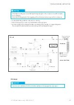
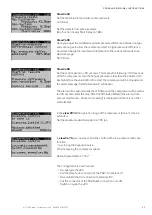
Shunt reactor to compensate 
reactive current

Programmable alarm output:
voltage free contact (up to 240 VAC)

3-phase voltage supply

Relay K41 for transmission of the HP 
alarm to the C7000

High pressure switch, circuit 1

µPC board

Inverter connections

Mains filter

terminal Assignation

Use

3

0V

RS485/ModBus® 

connection

4

RX+/TX+

5

RX–/TX–

6

PTC input

not used

7

24VDC

auxiliary voltage

8

0V

9

STOa

input for HP alarm

10

STOb

1, 2

Relay output

not used

Summary of Contents for CyberLab

Page 1: ...CyberLab Original instructions Precision Air Conditioning Units 400V 50Hz 3Ph N PE Index G17F Issue 2 2018...

Page 2: ...ts air conditioning technology business spe cialising in A C for data centres and telecommunications installations STULZ has seven production plants Germany Italy the USA 2 in China Brazil and India a...

Page 3: ...TULZ Cyberlab is a precision air conditioning unit which has been developed especiallyfor applications with a low or no heat load applications howeverforwhich temperature and humidity need to be kept...

Page 4: ...4 4 EN 02 2018 G17F STULZ GmbH all rights reserved CYBERLAB ORIGINAL INSTRUCTIONS...

Page 5: ...Installation 17 5 1 Selection ofthe installation site 17 5 2 Positioning the unit 18 5 3 Connection ofthe piping 20 5 3 1 Refrigerant piping 20 5 3 1 1 Design 20 5 3 1 2 Position ofthe refrigerant co...

Page 6: ...ey must be permanently available at the place where the system is used danger Works have to be carried out by competent staff only Safety devices may not be bypassed 1 3 Handling refrigerants Get qual...

Page 7: ...in case of repairs and repeated inspection must be ensured Repeated inspection according to EN 378 The operator is responsible forthe execution The operator must ensure that all maintenance inspection...

Page 8: ...der number 10 Additional customer requirements notice When delivery is accepted check the unit against the delivery note for completeness and for external damage and record it on the consignment note...

Page 9: ...be carried out to protect the unit from damage and corrosion the storage point must not be exposed to direct sunlight Observe the storage conditions in the chapter Application limits store the unit p...

Page 10: ...wicht max filling change charge max de rempliss kg A U 1 S 21 AL EN 02 2018 G17F STULZ GmbH all rights reserved cyberlab original instructions Cooling system A air cooled L laboratory unit with speed...

Page 11: ...mperature in case of a small thermal load To achieve a dehumidification the electronic expansion valve is partially closed in the first step The reduction ofthe refrigerant mass flow makes the evapora...

Page 12: ...l surfaces Revision glasses through which the state of pollution in the interior ofthe air conditioning unit can be checked are integ rated in the side panels The filter positon and the state ofthe co...

Page 13: ...hotgas reheat is switched on Humidity control The humidity is controlled bythree components 1 electronical expansion valve 2 speed controlled compressor EC compressor 3 optional external humidifier If...

Page 14: ...ferent from the standard voltage 400V 50Hz 3Ph N PE In this case see the technical data bythe help ofthe Stulz Select planning tool The unit design the external dimensions the weight the position and...

Page 15: ...alues for upflow units assume an installed discharge duct 4 2 Technical Data DX cooling cap R410A total 24 C 45 r h sensible kW 20 1 20 1 Airflow m h 6000 max external pressure Pa 450 Return airfilter...

Page 16: ...16 EN 02 2018 G17F STULZ GmbH all rights reserved cyberlab original instructions 4 3 Dimensional drawings Front view Side view Projecting main switch...

Page 17: ...nimals may not have access to the installation site ofthe A C unit check that the installation site is appropriate forthe unit weight which you can read in the technical data take into account the nec...

Page 18: ...as close as possible to the installa tion site keep at hand mounting aids at the left and right unit side lift the units with a fork lift by 50mm remove the pallet put the mounting aids at the left a...

Page 19: ...and secure them against slipping push the unit on the scantlings bytwo persons put the mounting aids at the left and right unit side lift the support surface ofthe mounting aids at a sufficient height...

Page 20: ...iptions pressure pipe and liquid pipe The lines to be connected have to be soldered Forthe connection ofthe external pipework note the pipe entrance area shown on top ofthe page 5 3 Connection of the...

Page 21: ...line and the liquid line each a non return valve is supplied loose with the A C unit Forthe liquid line we recommend to install the non return valve nearthe condenser this avoids the return flow of r...

Page 22: ...tion right bottom Syphon installation Ensure that there is a sufficient height difference between the fan pan and the upper bow ofthe syphon orthe high est part ofthe drain tube in orderto avoid a wat...

Page 23: ...lumn remains in the drain the water does not drain off and fills the fan pan This water can be drawn dropwise in the fan or can drop out of the unit through the panels ifthe pan is full unit limit pos...

Page 24: ...the connection cable is de energized The electric cables are onlyto be connected by an authorized specialist notice Make sure that the phase rotation is correct the rotating field must turn right Oth...

Page 25: ...y cable in the unit as shown in the following illustrations and fix it at the unit frame route the electric cable into the electrical box from below and connect the PE conductor at the PE rail the neu...

Page 26: ...are installed and connected in the A C unit Commissioning The reheats are controlled and monitored bythe controller ofyourA C unit No further measures are required for commissioning Operation The reh...

Page 27: ...ofthe air conditioning unit it must be ensured that it is operated bytrained staff and that inspection and maintenance work is carried out in the intervals listed in the chapter Maintenance The operat...

Page 28: ...some cases this must be decided bythe installer according to the ambi ent conditions on site warning Risk of injury by burns in case of contact with refrigerant In case of a defective filling line ref...

Page 29: ...s running Stop the filling once you see only small bubbles in the sight glass Note the weight ofthe refrigerant bottle and determine the quantity of charged refrigerant This is helpful for later inspe...

Page 30: ...witch on the A C unit at the master switch The controller is now supplied with power so you can use it for adjustments make sure that the air cooled condenser is operating 6 2 Control of the electrica...

Page 31: ...0Advanced Terminal Start stop key open the electrical box doorwith the main switch switched on connect a notebook at the service port X15 on the C7000IOC board to carry out possible configurations set...

Page 32: ...pressing the Start Stop key on the C7000AT controller or bytyping the command state start on the notebook Check after 20 minutes operation whether bubbles are visible in the sight glass ofthe liquid l...

Page 33: ...onfiguration of PC not permanently connected Digital input Assignation of block J4 ID1 ID2 ID3 ID4 set on 0V Compressor start stop with ramp ID5 Compressor start stop without ramp ID6 Alarm reset ID7...

Page 34: ...to the PC must be removed De energize the PC Open terminal ID7 remove the 0Vvoltage Pull the connector ofthe ModBus connection from J8 Push the telephone connector ofthe PGD1 on to block J7 Switch on...

Page 35: ...fault Yes Bythis setting the inverter is initialized suitablyto the com pressor It is compellingly required to select Yes Following the data is written in the inverter The program verifies the compati...

Page 36: ...Go back to M01 using ESC orfasterwith Prg Bythe PRG keyyou get to view M01 the first window in the main menu branch With the Enter keyyou procede to the next menu Now select M06 BLDC means Brushless d...

Page 37: ...1c can be extended Set the maximum admitted speed on 120 rps In view Co15 you can adjust howthe control with a low pressure ratio shall function 1 by closing the expansion valve 2 by increasing the co...

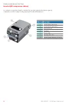
Page 38: ...e PC controller the inverter modulates the rotation speed of compressor in orderto adjust cooling capacityto the actual thermal load Reference Description A Terminal block for power lines B Terminal b...

Page 39: ...e free contact up to 240 VAC 3 phase voltage supply Relay K41 fortransmission ofthe HP alarm to the C7000 High pressure switch circuit 1 PC board Inverter connections Mains filter Terminal Assignation...

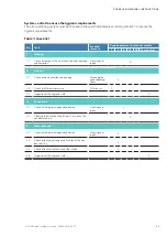
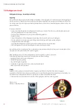
Page 40: ...ed and qualified specialist staff Procedure instructions carry out work on the system onlywhen it is shut down switch offthe A C unit at the controller and at the master switch display a DO NOT SWITCH...

Page 41: ...corrosion Cleaning and repair X 2 Air filter 2 1 Check on contamination and damage Exchange the corresponding filters X 2 2 Check of differential pressure Filtertausch X 2 3 Inspection ofthe hygienic...

Page 42: ...r drier cartridge evacuate the refrigerant circuit resp the closed off section by a vacuum pump fill the refrigerant circuit with the refrigerant named on the type plate An overfilling ofthe circuit m...

Page 43: ...anufacturer The EC compressor has no oil sight glass Operating with incorrect quantity of oil will in case of overfilling and lack of oil cause a function failure Expansion valve The refrigerant circu...

Page 44: ...An increased operation current indicates a winding short circuit in the fan motor Air filter Afilter monitor controls the state ofthe filter As soon as the pressure loss exceeds an adjustable value a...

Page 45: ...range AB according to the Robert Koch Institute for example Incidin Perfect from Ecolab Remove contaminated insulations from tubes and all sealing gaskets and replace these by new ones When working wi...

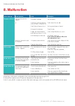
Page 46: ...d 1 Fan motor defective Fan speed too low Check fan motor on voltage continuity and cur rent consumption Check iffan is mechanically blocked 2 Airfilter extremely clogged Check airfilter 3 Hoses to th...

Page 47: ...the atmosphere but must be returned to the manu facturer if it is not reused The ester oil in the compressor must also be disposed of As it contains dissolved refrigerant it can not be disposed of li...

Page 48: ...isted below In the case of a modification ofthe equipment not co ordinated with us this declaration loses its validity Air conditioning unit 10 Contents of the CE Declaration of Conformity The undersi...

Page 49: ...idifier 11 Options Item 1 Ion exchanger Water supply BNB humidifier illustr similar Item 3 Leitwertf hler Item 7 PE tube Sensor line Power line Control line PE conductor Install the BNB according to t...

Page 50: ...nnection for demineralized drinking water at the BNB according to page 43 BNB manual Plug the PE tube item 7 into the connector item 5 and conduct it to the water supply ofthe BNB Shorten the PE tube...

Page 51: ...th a plug which you must insert on the connectors at the rear side ofthe BNB A PE line lies reeled up in the lower section ofthe CyberLab unit Route the PE line through the openings shown below out of...

Page 52: ...0257 ventas stulz com mx netherlands STULZ GROEP B V Tel 31 20 54 51 111 Fax 31 20 64 58 764 stulz stulz nl new zealand STULZ New Zealand Ltd Tel 64 9 360 32 32 Fax 64 9 360 21 80 sales stulz co nz po...

Reviews: