STULZ CyberRow Chilled Water Series Installation, Operation & Maintenance Manual
(
Dec.
, 2013)
4-11
The
E2
controller continually analyzes the demand for
cooling, humidifying and dehumidifying against the control
set points and determines the appropriate response (control
output signals) to operate the A/C system. The controller
is equipped with analog input positions for monitoring
temperature and humidity sensor(s). The controller
monitors the actual cold aisle supply air conditions for
three fan zones (upper, middle and lower) as measured by
temperature sensors mounted locally to each zone inside
the CyberRow cabinet. The controller also monitors a
temperature/humidity (T/H) sensor which is mounted in the
return (hot aisle) side of the cabinet.
A remote mounted supply air T/H sensor may also be
provided as an option. The controller may be confi gured
by the factory to manage system operation based on the
remote T/H sensor inputs which is to be fi eld installed in the
supply (cold aisle) space.
4.4.1 Control
Signals
Control output signals and alarm recognition takes place
by means of the controller analyzing signal inputs from
the sensor(s) and developing the appropriate digital or
proportional response.
4.4.1.1
On/Off Digital Control
Based on control inputs, the controller provides an on/off
output signal to activate certain modes of operation for
the air conditioner (i.e. humidifi er, fans, or annunciate an
operating condition status i.e. alarm condition).
4.4.1.2
Proportional/Integral (P/I) Control
The controller calculates proportional control output
signal(s) based on the analysis of input signals which
then determines the air conditioner's required mode(s) of
operation. Signals representing temperature and humidity
are each compared by the controller as a percentage value
to the maximum control setpoint value resulting in control
output values that are directly proportional to the input
signal.
The integral value is used to gradually adjust the
proportional output when the calculated output does not
move the process variable closer to setpoint in a given
period of time. Decreasing the integral value decreases
the interval for the output corrections (speeding the rate
of adjustment). Increasing the integral value increases the
interval for corrections (slowing the rate of adjustment).
4.4.2 Control
Methods
System operation depends on the controller's programmed
operating confi guration. Control takes place by means of
the controller analyzing signal inputs from the supply air
temperature sensors and the return air T/H sensor or optional
remote mounted supply T/H sensor. The
E2
controller may
be confi gured for temperature/relative humidity control
(standard) or dewpoint control (optional) for cooling,
dehumidifi cation and humidifi cation functions.
The control method, selected in the Factory menu, deter-
mines which sensors the controller uses to manage opera-
tion of the A/C system. You may view the method selected
in the Control>Set menu, see Section 4.5.4.1.
Control Method
Control Sensor Selection
Temperature
control
1. Supply air sensors
2. Return T/H sensor
3. Remote Supply T/H sensor
Humidity control
1. Return T/H sensor
2. Remote Supply T/H sensor
Dewpoint control
1. Return T/H sensor
2. Remote Supply T/H sensor
4.4.2.1 Temperature/RH
Control
When enabled for temperature/RH control, the controller
continuously monitors the selected combination of air
temperature sensors and return T/H sensor or optional
remote supply T/H sensor, as confi gured by the factory, to
manage system operation.
4.4.2.2 Dewpoint
Control
When enabled for dewpoint control, the controller logically
examines the combination of temperature and relative
humidity (dewpoint) and determines the proper control of
cooling, humidifi cation and dehumidifi cation to move the
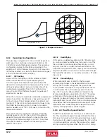
actual conditions to within the boundaries of the dewpoint
set points as they would appear on a psychrometric chart
(see Figure 13). It avoids scenarios where the A/C unit might
both cool and humidify the supply air when cooling alone
will achieve the desired result.
The controller calculates dewpoint using the control
inputs from the return air T/H sensor or optional remote
mounted supply T/H sensor as confi gured by the factory.
The calculated dewpoint property is used to manage system
operation which results in higher operational effi ciency and
shorter component run-times.

