(April, 2013)
DRH Series GEN1 Ultrasonic Humidifi er Installation, Operation & Maintenance Manual
4-8
4.4 Common Repairs/Parts Replacement
When parts are replaced, refer to sections “4.4.1 Preparation for
Repairs” and “4.4.2 Re-assembling”.
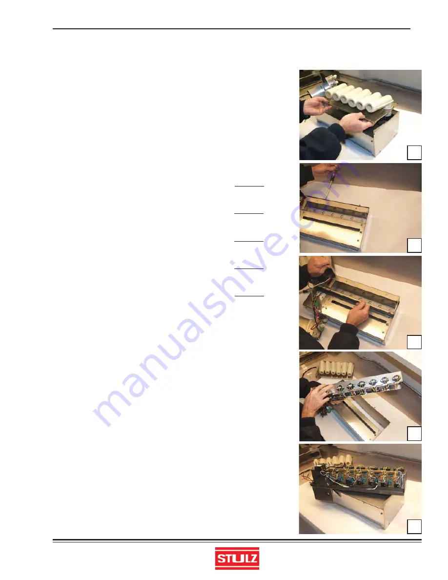
4.4.1 Preparation for Repairs (Removal of Water Tank)
1) Stop the humidifi er, set the power supply circuit breaker (main
switch) to “Off” and close the water supply valve.
2) Drain the water tank.
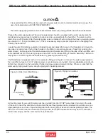
3) Remove the air fl ow guide (water tank cover) mounting
screws from the top of the humidifi er and remove the air fl ow
guide.
Photo 17
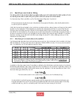
4) Remove the water tank mounting screws from the humidifi er
fan casing.
Photo 18
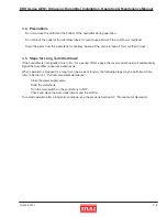
5) Lift the water tank from the base and place it on a well lit work
surface for removing/replacing the parts.
Photo 19
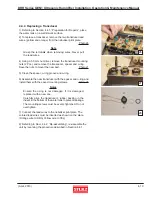
6) The transducers are visible when you rotate the tank to view
the bottom.
Photo 20
7) The nebulizer print plates are on the side of the tank adjacent
to the transducers.
Photo 21
4.4.2 Re-assembling
1) Before re-assembling the humidifi er, confi rm there is no wa-
ter leakage by pouring water into the tank.
2) When re-assembling after replacing parts, inspect the interior
and check the following points:
All the screws must be securely tightened.
All the lead wires must be correctly and securely connected.
(Special attention should be paid to the fan lead wires.)
All the plates, boards and relays must be free from discoloration,
deformation and deterioration.
Electrical wires must not be damaged.
3) After re-assembly is completed, supply water and power to
the unit and turn it on. Check to see that normal nebulizing mist
is visible from all the mist blow tubes and that there is no water
leakage.
17
18
19
20
21


