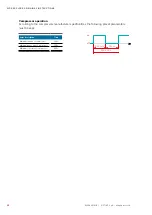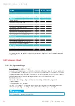
62
EN/06.2016/i01 © STULZ S.p.A. – all rights reserved
WPA ExPlOrEr OrIGINAl INSTrUCTIONS
WArNING
Make sure that the phase rotation is correct, the rotating field must turn right!
The compressor is dependent on correct phase rotation. The sense of rotation will be checked
at the factory before dispatch. An inverse rotating field would damage the compressor.
The asymmetry of phase between the conductors may amount to 2% maximum.
To determine the asymmetry of phase measure the voltage difference between the phase con-
ductors (L1-L2, L2- L3, L1-L3) and calculate the average value of the measured voltages. With
a voltage supply of 400V/3Ph/50 Hz, the maximum deviation to the average value of the volt-
ages may not exceed 8 V .
Alternatively, you can check the phase rotation by using the controller. For this, close the electri-
cal cabinet and turn the main switch to position I. If the phase rotation is incorrect, the controller
display shows an alarm symbol.
After fixing the phase rotation, make sure that the unit is turned OFF.
The electronic control board provides digital outputs for alarm signals and status of the unit. The
assignment of outputs to different alarms and status data can be configured in the controller
unit. The default configuration is shown in the specific wiring diagram of the unit.
INFOrMATION
The digital inputs of the controller board are disabled by default. If needed, enable them in
the software. For more information check the controller manual.
6.11 Pump control
The unit's microprocessor controls internal and external pumps, as well as monitoring a pump
alarm.
6.11.1 System with external pump
Choose a power switch and a contactor in respect of the pump capacity. A power switch and a
contactor can be located in the electrical box.
WArNING
If you do not explicitly order the load outlet option, the power to the external pumps cannot
be supplied by the main switch on the unit as the main switch is only designed for the
current consumption of the standard unit itself. The pump must be individually provided with
safety elements.
Design the wiring between the controller and the contactor with reference to the connection
diagram for the controller and the wiring between the pump and power switch according to the
manufacturer's notes.

