26
/07.2016/
G20
EN
6.4 Electrical connection
Connection of the power supply cable
The power supply system on site and the pre-fuses must be designed for the total current of the unit (see technical
data).
Route the electric cable into the electrics box from below and connect the hree phases to the main switch, the PE
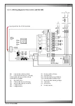
conductor at the PE rail and the neutral conductor at the neutral terminal, in accordance with the wiring diagram
(part of the unit documents) and secure these cables by the pull relief screw.
Make sure that the phase rotation is correct, the rotating field must turn right !
For use of leakage-current (FI) circuit breakers, EN 50178 5.2.11.2 must be taken into account. Only
type B pulse-current FI circuit breakers are permitted. FI circuit breakers do not provide protection
against bodily harm during operation of the unit or frequency converters.
Make sure that the power supply corresponds to the indications on the rating plate and that the tolerances
according to the "Application limits" are not exceeded.
In addition to this, the
asymmetry of phase
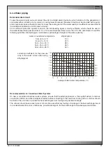
between the conductors may amount to
2% maximally
. The
asymmetry of phase is determined by measuring the voltage difference between the phase conductors.
The average value of the voltage differences may not exceed 8 V.
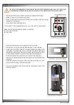
The scroll compressor is dependent on correct phase
rotation. The sense of rotation will be checked at the
factory before dispatch. On site, if the rotating field of the
compressor is incorrect, it must be corrected by changing
two phases of the power supply at the isolator. An inverse
rotating field can be detected by a raised compressor
noise level and results in overheating and destruction of
the compressor after several hours of operation.
Ensure that the electric cables are de-energized.
The electric cables are only to be connected by an authorised specialist.
The unit must dipose of an effective earthing.
Do not touch electronical components, without taking care of protective ESD measures.
Summary of Contents for Mini-Space DX CCD131A
Page 13: ...07 2016 G20 13 EN 5 3 Dimensional drawings Cabinet size 1 Cabinet size 2...
Page 36: ......
Page 58: ...10 01 2017 air_MSDX 150 1000 810 700 160 920 EN Size 2 Filter top with flexible duct...
Page 62: ......
Page 66: ......
Page 70: ......
Page 73: ......

