-
36
-
© STULZ GmbH, Hamburg
-
36
-
7.4 Shut-down
During seasonal shut-down or alternatively shut-down for maintenance of the electrical parts and/or the plumbing, the
humidifier should be pla ced out-of-service.
NOTE:
The water cylinder should be emptied before shutting down the humidifier, to prevent corrosion of the elec-
trodes.
Follow the instructions below:
• open the mains power switch to the humidifier;
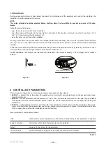
• open the rocker switch located in the lower right on the frame of the structure, placing it in position 0 (see Figs. 7.2.3.2
and 7.4.1) and checking that the display is off;
• close the water shut-off tap to the humidifier.
If during a shut-down the cylinder needs to be emptied, before disconnecting power from the unit press the drain button
(see Fig. 7.2.3.2), to open the drain electrovalve, and hold it manually in this posi tion until the water has been completely
emptied.
In the event of malfunction of the drain electrovalve, the cylinder can be emptied manually by removing it from the connec-
tion manifold and slowly pouring the water into the bottom collection tank.
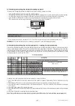
For the humidifiers 25 to 65kg/h, use the manual drain device on the manifold, (see fig. 7.4.2) drawing it until it makes a
release.
Fig. 7.4.1
Fig. 7.4.2
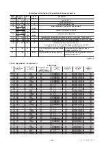
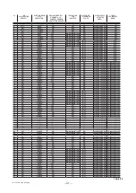
8 CONTROLLER H PARAMETERS
The numerical, configuration and control parameters are grouped into three levels:
1.
LEVEL 1
– set point, that is, the value of the appliance’s main setting St, accessible directly via the keypad for both read-
ing and modification.
2.
LEVEL 2
– control parameters and measurements, that is, the physical vales measured and the operating parameters
involving the control of the humidification process; these too can be accessed directly via the keypad for reading and
modification.
3.
LEVEL 3
– configuration parameters consisting of the data needed to customise the controller, according to the require-
ments of the humidifier. These parameters are can be accessed only by password, to prevent the unwanted modification
of the configuration and thus the humidifier’s essential functions.
Each parameter is composed as follows:
code
alphanumeric symbol appearing on the display corresponding to the parameter in question
range of variation
limit values within which the parameter can be modified
default
value set in the factory for the parameter
unit of measure
symbol displayed showing the unit of measure used for the parameter
Tab. 8.1
manual drain device
OFF


