Installation
STULZ UltraWater 3-stage reverse osmosis system SUW
© STULZ GmbH, Hamburg
- 22 -
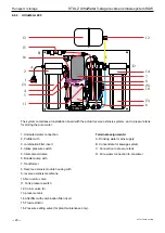
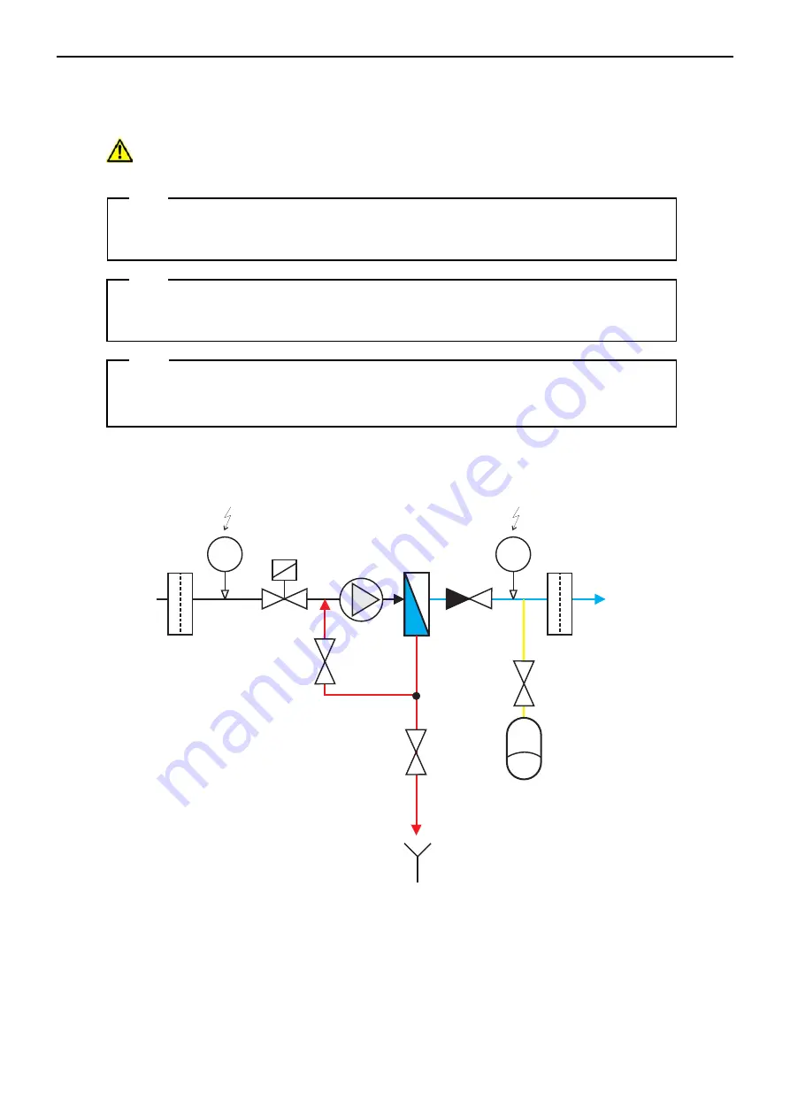
Permeate =
pure water
(approx.0...3bar)
Feed=
supply
(1...5bar)
p
RO module
Non-return
valve
Drain valve
or ball valve
with aperture
Working
pressure
valve
Pump
Prefilter
p
Afterfilter
Pressure tank
(membrane expansion tank)
I-O
-P
lan
R
O
-E
X
C
EL
-D
TP
-1
-1
.C
D
R
V
ers
ion
2:2
6.0
7.2
01
4
B
.R
am
sch
U
m
ke
hro
sm
ose
an
lag
en
Ex
cel
D
TP
(3)
1:1
M
aß
sta
b:
M
ate
ria
l:
G
m
bH
&
Co
.K
G
A
qu
aC
are
A
m
W
ies
en
bus
ch
11
D
-4
59
66
G
lad
be
ck
G
erm
an
y
ph
on
e:+
49
-2
0
43
-3
75
75
8-0
fax
:+
49
-2
04
3-3
75
75
8-9
0
em
ail:
inf
o@
aq
ua
ca
re.
de
Intake pressure switch
Function: NO
Hysteresis:approx.0.5...1.0bar
Inlet
solenoid valve
Function: NC
Tank pressure switch
Function: NC
Hysteresis:approx.2.0-3.0bar
Tank
valve
Concentrate =
waste water
(0...0.5bar)
Note:
Connection of the pressure tank is absolutely essential for reliable operation of ultrasonic
humidifiers with the reverse osmosis system!
Install a pressure reducer upstream of the system, which restricts the
intake pressure to max. 4 bar.
Note:
Note:
During installation, the reverse osmosis system must be separated from the drinking wa
-
ter mains by a backflow preventer.
In sensitive areas where leaks must be avoided at all costs, we recommend the use of a
leakage warning system. This will cut off the water supply in the event of a leak.
7.2. Connection diagram

