background image

EN/

0915/WLA Compact

/38

The factory setting of the by-pass is for operation with pumps 
50 Hz.

For the correct operation with a power supply 
frequency of 60 Hz it is necessary to change the 
calibration of the automatic by-pass according to 
the following table.

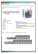
Automatic by-pass

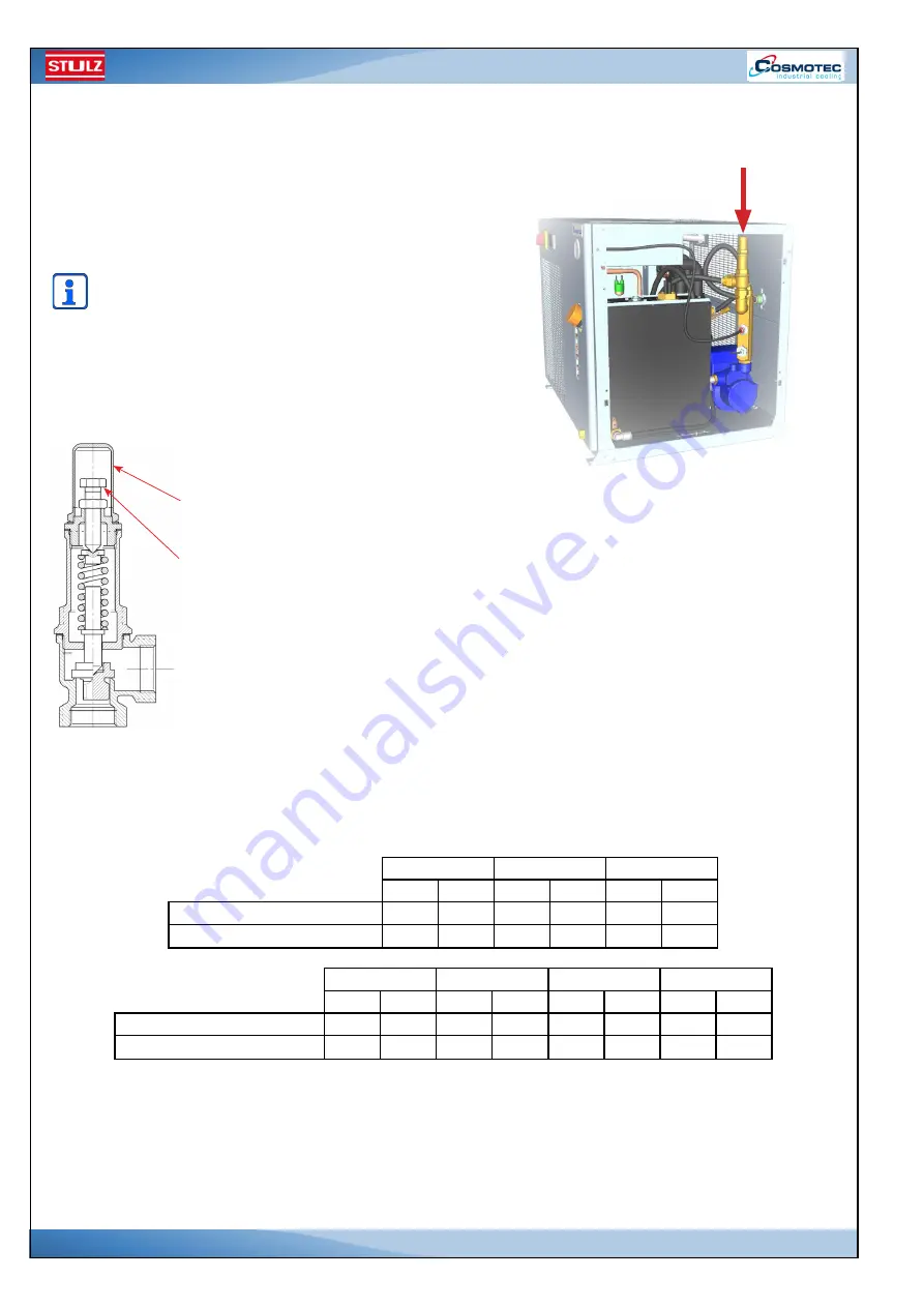
The automatic by-pass (BPA) is located on the right side of the chiller, and is accessible by removing the right panel.

Below the setting values of the automatic by-pass recommended by the manufacturer:


WLA-WLL 12

WLA-WLL 15

WLA-WLL 22

50 Hz

60 Hz

50 Hz

60 Hz

50 Hz

60 Hz

standard pump [bar]

2,6

3,3

2,5

3,2

2,3

3,0

middle pressure pump [bar]

4,2

5,8

4,1

5,8

4,0

5,5

WLA-WLL 23

WLA-WLL 30

WLA-WLL 34

WLA-WLL 44

50 Hz

60 Hz

50 Hz

60 Hz

50 Hz

60 Hz

50 Hz

60 Hz

standard pump [bar]

2,3

3,0

3,7

4,8

3,7

4,8

3,5

4,5

middle pressure pump [bar]

4,0

5,5

5,0

6,8

5,0

6,8

4,5

6,0

To calibrate the bypass:
• 

remove the right side panel of the chiller

• 

close the valves on the external flow pipe

• 

activate the pump and on the pressure gauge display the working 
point

• 

remove the top cap of the valve by-pass

• 

with chiller operating and the pump turned on, act on the calibration 
screw until bringing the pump within the range of correct operation

• 

replace the top cap

• 

open the taps on the external flow pipe.

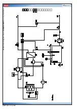
Cappuccio

Vite di taratura

Chec

k on 

MANU

AL P

AR

T II

 for an

y modif

ication.

Summary of Contents for WLA Compact Series

Page 1: ...LZ the natural choice W L A C M PA C T ENGLISH EN WLA Compact Air cooled water chiller 230 1 50 230 1 60 400 3 50 460 3 60 Instructions Translated instructions Index 04 Revision 09 2015 STULZ S p A It...

Page 2: ...nd technologies to obtain an high quality chiller The CE mark guarantees that the STULZ Cosmotec products satisfy the requirements of the European Machinery Directive for safety The level of quality i...

Page 3: ...n components of the refrigerant circuit 26 4 6 Hydraulic diagrams 26 4 7 Components of the hydraulic circuit 27 4 8 Air circuit 27 4 9 Protection and control electric components 27 5 Technical data 29...

Page 4: ...rature fluid up to 5 C code OC10TW0 OC20TW0 58 12 3 Device for low ambient temperature up to 5 C code OC10TM0 OC20TM0 58 12 4 Device for low ambient temperature up to 10 C code OC10TL0 OC20TL0 59 12 5...

Page 5: ...sistance perform routine and special maintenance and repairs Qualified personnel are those who thanks to their training education experience and specific knowledge regarding occupational standards are...

Page 6: ...a shown in the drawings in paragraph 5 3 Interventions on the electric hydraulic and refrigerant equipment must be carried out by qualified personnel Disconnect the unit power supply before working on...

Page 7: ...sk Preventive measures Close to the unit Projection launch of various tools and small parts screws nuts washers etc that may fall accidentally on the fan impellers Bruises shocks During installation m...

Page 8: ...tem Wear PPE During maintenance Area Danger Risk Preventive measures Close to the unit Leaks in the refrigerant circuit defective safety valve and high pressure switch fire defect on the gas charge li...

Page 9: ...y biodegradable Physical and chemical hazards thermal decomposition in toxic and corrosive products Additional indications Not dangerous according to Directive 1999 45 EC 4 FIRST AID MEASURES Inhalati...

Page 10: ...with water jets from a protected position If possible use vaporised or sprayed water to remove the fumes Special protection equipment for fire fighters Use respiratory equipment Standard protection c...

Page 11: ...the supplier Never repair or modify the valves of the containers or of the safety devices Damaged valves must be signalled to the supplier immediately Keep the container valves clean and free from con...

Page 12: ...ce Protect the eyes face and skin from liquid sprays Wear safety glasses with side protection Wear safety glasses with side protection or goggles during top up operations or sleeve disconnection Stand...

Page 13: ...l water partition coefficient log Kow 0 94 Auto ignition temperature C Not applicable Viscosity 20 C mPa s Not applicable Explosive properties Not applicable Oxidizing properties None Other data Gas V...

Page 14: ...sh mg l 450 Persistence and degradability Not readily biodegradable Potential for bioaccumulation Considered to be not bioaccumulative due to a low log Kow log Kow 4 Mobility in soil Due to its high v...

Page 15: ...DR ADNR RID Label 2 2 EmS Number IMDG F C S V Marine Pollutant IMDG No 15 REGULATORY INFORMATION Specific laws and regulations concerning safety health and environment for the substance or mixture EU...

Page 16: ...ller water supply Position close to the hydraulic circuit outlet connection Hot components Position close to condenser inlet outlet pipes under the protection guard and on the compressor support With...

Page 17: ...taining HFC fluids causing greenhouse effect regulated by Kyoto protocol Das Ger t erh lt wie vom Kyoto Protokoll geregelte Fluorkohlenwasserstoffe Treibhausgasen Dispositif contenant fluides HFC effe...

Page 18: ...ndards in force and instructions provided in this manual Moreover its use is prohibited in the event it is installed incorrectly on mobile parts or on oscillating inclined not levelled supports or on...

Page 19: ...0 W 1 15 1500 W 1 30 2800 W 1 22 2200 W 1 34 3400 W 1 1 a 50 Hz W15L32 44 4400 W 1 Liquid chiller 10 heat exchanger only 20 heat exchanger standard pump 30 heat exchanger medium pressure pump 40 heat...

Page 20: ...h cable gland sheaths The compressor is fixed to the base and it is found in the left rear side of the chiller accessible by removing the left side panel The condenser with intake fan integrated is lo...

Page 21: ...0 1 A L W 1 2 3 4 5 6 7 9 8 10 11 12 13 14 EN 0915 WLA Compact 21 Standard circuit diagram Check on MANUAL PART II for any modification...

Page 22: ...0 2 A L W 1 2 3 4 5 6 7 9 8 10 11 12 13 14 3 0 EN 0915 WLA Compact 22 Standard circuit diagram Check on MANUAL PART II for any modification...

Page 23: ...EN 0915 WLA Compact 23 Standard circuit diagram Check on MANUAL PART II for any modification 0 4 A L W 1 2 3 4 5 6 7 9 8 10 11 12 13 14 5 0...

Page 24: ...EN 0915 WLA Compact 24 Standard circuit diagram Check on MANUAL PART II for any modification 0 4 L L W 1 2 3 4 5 6 7 9 8 10 11 12 13 14 5 0...

Page 25: ...ing aggressive atmosphere Fan Installed on the rear side of the condenser this intake fan is not duct type The fan with metal blades is provided with metal protection grid Evaporator The plate heat ex...

Page 26: ...or outlet probe placed on the water circuit measures the temperature of the cooled liquid If this reaches values equal to or lower than the alarm threshold the control disables the cooling mode 4 6 Hy...

Page 27: ...Specific options for the management of the chiller at low ambient temperatures allow you to adjust the speed fan as indicated below on off to reach a maximum ambient temperature of 5 C speed modulati...

Page 28: ...rically connected to the microprocessor board The electronic controller is equipped with a door for the sequencing with another regulator to reduce or optimise the chiller operation Moreover it is pos...

Page 29: ...e maximum and minimum flow rate values have been calculated considering a temperature difference between evaporator inlet and outlet equal to 3 C The operation of the heat exchanger is guaranteed if t...

Page 30: ...s F 2 8 5 6 11 2 Alkalinity dH 1 10 15 Concentration of chlorides mg l 20 50 100 Number of germs 1 CFU ml 1000 1000 1000 Langerlier saturation index 2 LSI 0 LSI 0 4 0 LSI 0 4 0 LSI 0 4 Water treatment...

Page 31: ...ers the contribution of the standard circulation pump 3 Inrush current compressor inrush current fan maximum operating current pump maximum operating current If glycol is added to the liquid to be coo...

Page 32: ...4 16 3 97 Inrush current A 19 7 19 7 19 7 19 7 AXIAL FAN N 1 1 Fan diameter mm 200 250 Air flow rate with free inlet m3 h 880 990 1820 1970 Power consumption W 64 78 115 150 Current consumption A 0 3...

Page 33: ...8 4 Inrush current A 29 26 32 30 AXIAL FAN N 1 1 Fan diameter mm 250 300 Air flow rate with free inlet m3 h 1820 1970 3410 3740 Power consumption W 115 150 115 150 Current consumption A 0 55 0 61 1 1...

Page 34: ...8 Inrush current A 47 61 AXIAL FAN N 1 1 Fan diameter mm 300 300 Air flow rate with free inlet m3 h 3410 3410 Power consumption W 230 115 Current consumption A 1 1 1 1 EVAPORATOR Flow rate of the flu...

Page 35: ...4 Inrush current A 15 7 16 32 30 AXIAL FAN N 1 1 Fan diameter mm 250 300 Air flow rate with free inlet m3 h 1820 1970 3410 3740 Power consumption W 115 150 115 150 Current consumption A 0 55 0 61 1 1...

Page 36: ...4 2 5 1 5 1 Inrush current A 24 22 4 32 31 AXIAL FAN N 1 1 Fan diameter mm 250 300 Air flow rate with free inlet m3 h 3410 3740 3410 3740 Power consumption W 230 350 230 350 Current consumption A 1 1...

Page 37: ...Pompa standard 50Hz 0 100 200 300 400 0 5 10 15 20 25 30 35 40 45 50 3 4 2 1 1 2 3 4 EN 0915 WLA Compact 37 Pump head Head kPa Flow rate l min Flow rate l min Head kPa Size No 1 WLA12 WLA15 WLA22 Size...

Page 38: ...2 6 3 3 2 5 3 2 2 3 3 0 middle pressure pump bar 4 2 5 8 4 1 5 8 4 0 5 5 WLA WLL 23 WLA WLL 30 WLA WLL 34 WLA WLL 44 50 Hz 60 Hz 50 Hz 60 Hz 50 Hz 60 Hz 50 Hz 60 Hz standard pump bar 2 3 3 0 3 7 4 8 3...

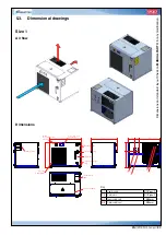
Page 39: ...ny modification Size 1 F1 Liquid supply 1 2 gas F F2 Fluid return 1 2 gas F A1 Power cable input 25mm A2 Signal cable input 25mm Key Safety label Electronic controller Main disconnection switch Pressu...

Page 40: ...urn 1 2 gas F A1 Power cable input 25mm A2 Signal cable input 25mm Key Safety label Electronic controller Main disconnection switch Pressure gauge Tank filing cap Visual level Air filter if available...

Page 41: ...S D F R H EN 0915 WLA Compact 41 Minimum distance from obstacles or other chillers Size Distance in millimetres mm S F D R H WLA 12 15 22 200 500 500 500 700 WLA 23 30 34 44 200 500 500 500 700...

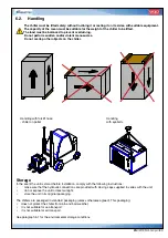
Page 42: ...nit serial number TSS maximum storage temperature Other labels of this type can be positioned on the packaging to identify the accessories included in the unit packaging Upon reception of the goods im...

Page 43: ...stored before installation comply with the following instructions make sure that the hydraulic connections are provided with closing caps supplied in series with the unit do not expose the unit to di...

Page 44: ...Moreover make sure that the site does not favour air short circuits between discharge and condenser recovery If the unit is installed on the ground the soil must not be soft or crumbly According to th...

Page 45: ...filter on the chiller inlet return pipe with metal mesh of 50 80 m Suitable insulation on the pipes to prevent condensation and reduce thermal on the circuit Before connecting the chiller to the util...

Page 46: ...arth cable to the PE clamp on the chiller electrical panel Some digital outputs of the electronic control are available to signal alarms and unit status The assignment of the outputs to the various al...

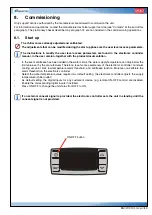
Page 47: ...that the power supply voltage falls within the values allowed for the unit and stated in paragraph 5 1 Close the protection panels of the electrical panel and take the main disconnection switch of th...

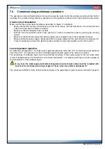
Page 48: ...ith the unit off open the specific cap on the top of the pump body and bleed the air Before starting the pump make sure that the impeller rotates freely If not use a screwdriver on the slot placed on...

Page 49: ...umentation In the event antifreeze has been added in the water circuit the water supply temperature can drop below the limit value set by the manufacturer Therefore reset some parameters of the electr...

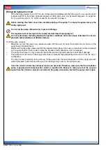
Page 50: ...istic curve of the pump installed at the power supply frequency Pump head on page 37 If required adjust it in order to take the pressure back to the pump operation field In the presence of reduced loa...

Page 51: ...the chiller to O OFF when possible or expose a warning sign such as DO NOT RESTORE POWER SUPPLY When the main switch is closed in position I the components are powered anyway even if the unit is set t...

Page 52: ...ents mechanical and chemical stress and to air pollution Dirt particles may deposit on the fins and reduce the heat transmission power besides increasing air flow resistance As a consequence the fan i...

Page 53: ...007 and Reg 1497 2007 and store registration of the maintenance activities in a specific register containing the various checks performed High pressure safety pressure switch the pressure switch is a...

Page 54: ...ircuit must be opened to replace a components refill the refrigerant circuit Perform the following operations if a leak is detected or if the circuit must be opened to replace a component 1 Collect th...

Page 55: ...or condenser see point vi failed fan s make sure that the liquid indicator indicates the presence of humidity in the system or of bubbles in the liquid indicator during normal operation Replace the ga...

Page 56: ...refrigerant circuit discharge dry the circuit replace the filter make vacuum and recharge open hot gas bypass valve check and or replace it 11 the chiller produces anomalous noise noisy compressor sc...

Page 57: ...isperse refrigerant gas in the atmosphere The refrigerant gas must be recovered by a chiller technician If not re used send it to an authorised collection centre Also the compressor oil must be recove...

Page 58: ...level with pump stop function Stulz code OC10EL0 OC20EL0 50 60 Hz medium pressure pump Stulz code OC10PM0 OC20PM0 Crankcase heater Stulz code OC10HR0 OC20HR0 Code Description Chiller set up Heat exch...

Page 59: ...wer supply poles N 4 4 Number of signal poles N 6 6 Rated voltage V 500 Rated current A 16 Pole material copper alloy passivated silver coating Insulation material group IIIa Cable connection section...

Page 60: ...n external probe connected electrically to the chiller electronic controller It allows you to track the temperature read by the external probe setting a minimum and maximum temperature limit Once thes...

Page 61: ...AC10EB0 AC20EB0 Handling wheels Stulz code AC10WH0 AC20WH0 Wall mounted brackets Stulz code AC10WM0 AC20WM0 Anti vibration mounts Stulz code AC10AV0 AC20AV0 Refer to the documentation attached to the...

Page 62: ...rding STULZ SpA products contact the local partner or branch The list is available on www stulz it STULZ S p A Via Torricelli 3 37060 Valeggio sul Mincio Verona VR Italy www stulz it Reception Aftersa...

Reviews: