Page 2
7.
In use, the FM Switch Wrench tightens a fastener. As soon as the wrench clicks a timer
on the wrench starts measuring time.
8.
When pressure on the wrench is released and the wrench resets, the timer stops and the
duration of the click is transmitted to the TCV. The TCV compares the duration of the
click to the TMIN and TMAX specification limits.
9.
The TCV immediately communicates to the operator the acceptability of that use of the
wrench. Light emitting diodes (LED’s) and a buzzer inform the operator whether or not
the wrench was used properly and the click accepted.
10. The TCV also uses the Input/Output Relays to communicate to programmable logic con-
trollers or other peripheral devices the acceptability, or lack of acceptability, of each use
of the wrench.
1.2
Component Nomenclature
1
Cabinet
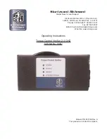
The Cabinet houses all of the electronic components in the unit. On the left and right sides
of the Cabinet there are flanges with holes for mounting the unit to an appropriate support.
2
Antenna Housing
The Antenna Housing protects the antenna for the 2.4Ghz band receiver.
3.
Power Light
Emitting Diode
(LED)
The power LED
lights and
remains lit
when electric
power is sup-
plied to the unit
and the power
switch is in the
“On” position.
4
Accept Light Emitting Diode (LED)
The Accept LED emits a green light to notify the operator when a wrench cycle meets the
duration specification.
5
Reject Light Emitting Diode (LED)
The Reject LED emits a red light to notify the operator when a wrench cycle has been
rejected.

