background image

Page 3

6

Strength/Prog Light Emitting Diode (LED)
In normal operation this Light Emitting Diode (LED) will emit green, yellow, or red light. If
the LED is green, the TCV is receiving a strong radio signal from the FM Switch Wrench
that it is working with. If it is yellow the signal strength is marginal. If this LED is red than
the signal strength is inadequate and the distance from the tool to the TCV should be
reduced. During programming this LED will be lit continuously to indicate the unit is in pro-
gramming mode.

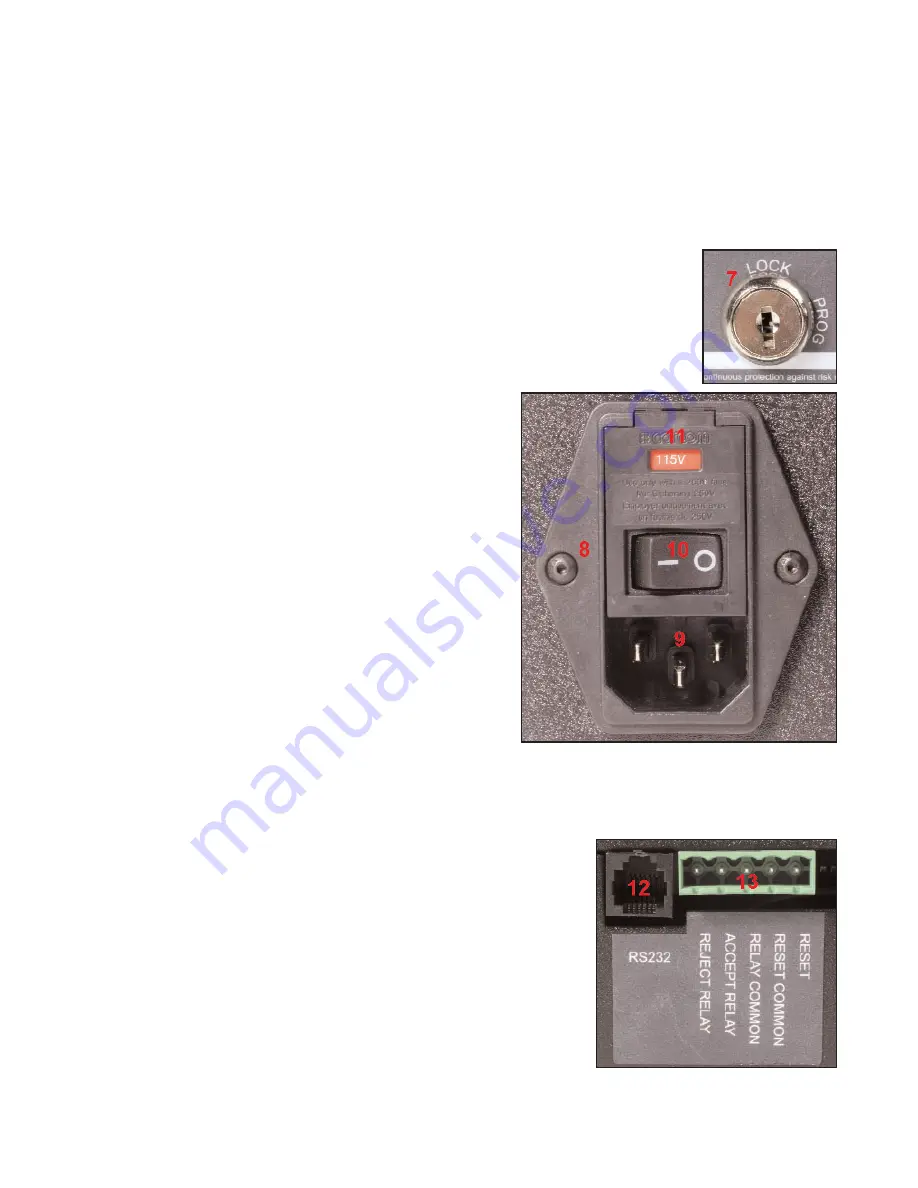
7

Key Lock
The  Key Lock permits and denies access to programming the unit.
When the Key lock is in the PROG position, programming functions are
enabled. When the Key Lock is in the LOCK position, the unit is in the
normal operating mode and only those functions are accessible.

8

Power Entry Module
The Power Entry Module houses the Receptacle
for the Power Cord, the Voltage Selector and Fuse
Holder, and the Power Switch.

9

Receptacle
The Receptacle accepts the female end of the
supplied Power Cord. The pronged end must be
plugged into a grounded outlet.

10

Power Switch
The Power Switch permits and denies electric
power to the TCV.

11

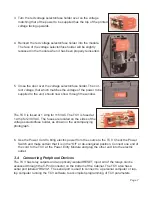
Voltage Selector/Fuse Holder

The Voltage Selector/Fuse Holder permits using
the TCV with either 115 VAC or 230 VAC electric
power sources. The correct power source must be selected during the installation process
and before electric power is supplied to the unit.

12

RS232 Communications Port
This port provides connection for the RS232 cable supplied
with the unit. The TCV is programmed with the supplied
software, and must be connected to the computer through
this port.

13

5-Pin Communication Receptacle
This receptacle mates with the supplied 5-pin connector,
and is used to communicate with programmable logic con-
trollers (PLC) and other devices.

14

5-Pin Connector

Summary of Contents for 10467

Page 1: ...p 3203 N Wolf Road Franklin Park IL 60131 Phones 847 455 8677 800 877 1347 Fax 847 455 0347 E Mail CustomerService srtorque com Web Site www srtorque com Operating Instructions Torque Control Verifier 2 4 GHZ S R Part No 10467 Manual P N 857269 Rev A This product is not RoHS compliant ...

Page 2: ......

Page 3: ...Table of Contents Contents Page Chapter 1 Introduction 1 Chapter 2 Domestic Warnings USA 4 Chapter 3 TCV Installation 5 Chapter 4 Programming and FM Communications 9 ...

Page 4: ......

Page 5: ...ply force after the click and overtorque the fastener 2 When the correct technique is used the torque wrench spends a certain amount of time in the clicked position When the wrench is used too quickly it spends less time in the clicked position When it is rotated past the click it spends more time in the clicked posi tion 3 The FM Switch Wrench is a preset clicker type torque wrench The torque is ...

Page 6: ...gic con trollers or other peripheral devices the acceptability or lack of acceptability of each use of the wrench 1 2 Component Nomenclature 1 Cabinet The Cabinet houses all of the electronic components in the unit On the left and right sides of the Cabinet there are flanges with holes for mounting the unit to an appropriate support 2 Antenna Housing The Antenna Housing protects the antenna for th...

Page 7: ...ule The Power Entry Module houses the Receptacle for the Power Cord the Voltage Selector and Fuse Holder and the Power Switch 9 Receptacle The Receptacle accepts the female end of the supplied Power Cord The pronged end must be plugged into a grounded outlet 10 Power Switch The Power Switch permits and denies electric power to the TCV 11 Voltage Selector Fuse Holder The Voltage Selector Fuse Holde...

Page 8: ... is a standard pc type cable and any cable of this type with a rated capacity of 120 VAC and 10 Amperes may be used 18 TCV Software The TCV software is supplied on the enclosed cd It must be installed on the computer that will be used to program the TCV before the TCV can be programmed and used 2 Domestic USA Warnings INSTRUCTION TO THE USER This equipment has been tested and found to comply with ...

Page 9: ...s Operation with non approved equipment is likely to result in interference to radio and TV reception The user is cautioned that changes and modifications made to the equipment without the approval of manufacturer could void the user s authority to operate this equipment 3 Installation There are two separate processes for installation the TCV must be installed in the location where it will be used...

Page 10: ...mounted but should still be accessible 3 3 Source Power CAUTION This unit is capable of being powered by 115 VAC or 230 VAC both 50 and 60Hz Before powering up the unit for the first time make sure the voltage selection on the power entry module matches the type of power being applied 1 The voltage setting for the unit is always displayed in a window above the power switch shown as 1 in the image ...

Page 11: ... at 1 Amp for 230 VAC The fuses are located on the sides of the voltage selector fuse holder as shown in the accompanying photograph 6 Use the Power Cord to bring electric power from the source to the TCV Check the Power Switch and make certain that it is in the Off or de energized position Connect one end of the cord to the TCV at the Power Entry Module and plug the other end into the electric ou...

Page 12: ...e must be installed and used to program the TCV before the unit is placed in service This software will work on machines using the Windows XP Professional operating system Close all programs not necessary to computer operation before executing the installation pro cedure below 1 Insert the TCV program compact disk into the compact disk drive on the computer that will be used to control the setting...

Page 13: ... small title window will open on the computer screen for a few seconds This window will close automatically and the CLK TUNE operating screen will be displayed Comm Port The software communicates with the TCV via serial communications through a 9 pin serial port on the computer Many computers have more than one communications port Use the mouse to select the port to which you have connected the TC...

Page 14: ...igher than the minimum pull time Once the number has been entered use the Enter key to make the value active and use the down arrow or mouse to go to the next parameter to be entered or action to be taken Time Between Cycles secs This is the minimum amount of time between wrench cycles clicks It is designed to help prevent the error of tightening the same fastener twice while missing another faste...

Page 15: ...et for later use The user can select the name of the parameter set for later recall Get Parameter Set Button This button is used to retrieve a previously stored parameter set Exit Button This button closes the window and exits the CLK_TUNE software If additional information is needed please contact us using the information provided on the front of the manual ...

Reviews: