21
en
10 cm
10
8
7
7
7
2,5
3
5
10
ph 2
0,4 x 2,5
2
1
3
4
5
6
7
8
9
10
11
12
13
14
15
16
17
18
19
2
1
3
4
5
6
7
8
9
10
11
10 cm
10
8
7
7
7
2,5
3
5
10
ph 2
0,4 x 2,5
2
1
3
4
5
6
7
8
9
10
11
12
13
14
15
16
17
18
19
2
1
3
4
5
6
7
8
9
10
11
10 cm
10
8
7
7
7
2,5
3
5
10
ph 2
0,4 x 2,5
2
1
3
4
5
6
7
8
9
10
11
12
13
14
15
16
17
18
19
2
1
3
4
5
6
7
8
9
10
11
10 cm
10
8
7
7
7
2,5
3
5
10
ph 2
0,4 x 2,5
2
1
3
4
5
6
7
8
9
10
11
12
13
14
15
16
17
18
19
2
1
3
4
5
6
7
8
9
10
11
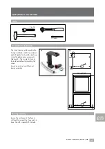
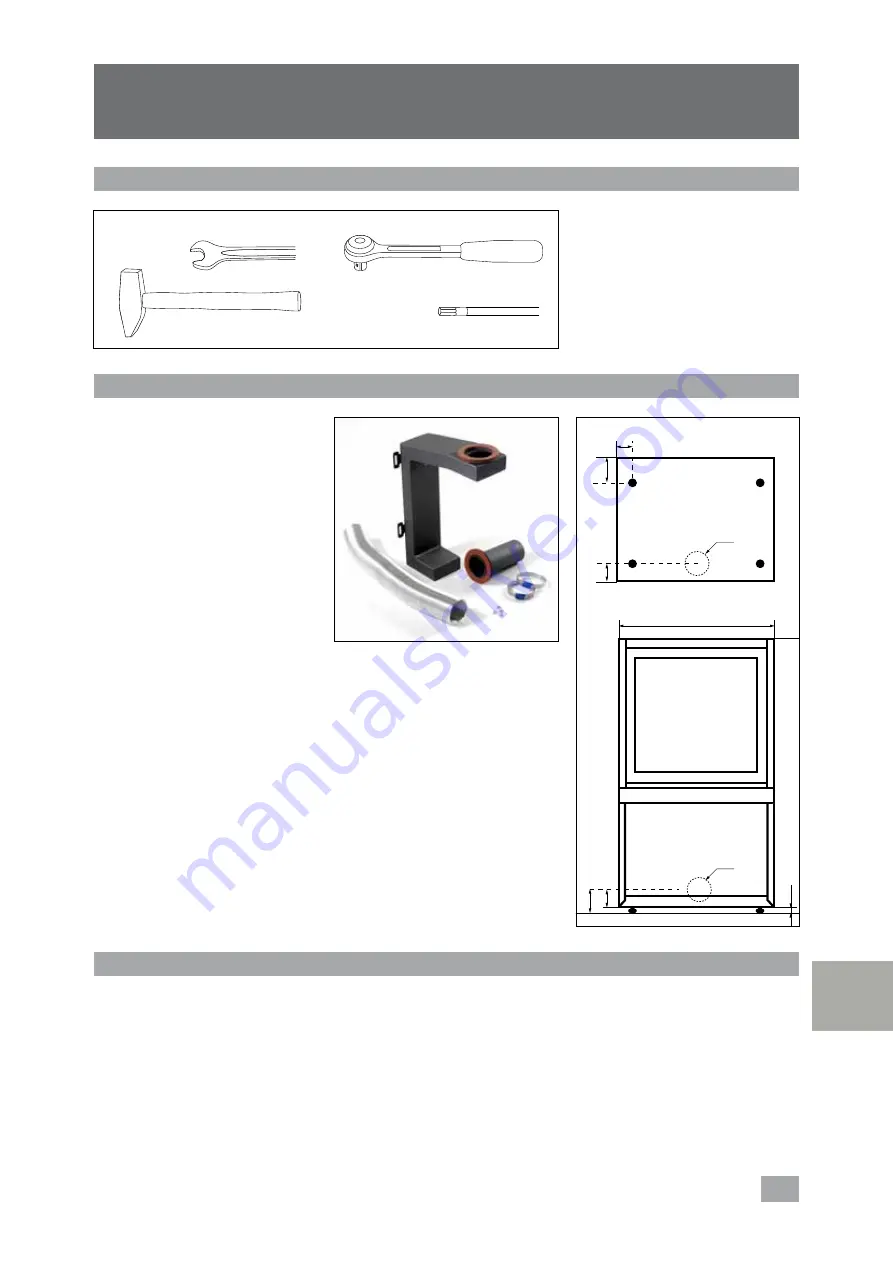
Air inlet for combustion
The stove requires air for combustion.
During installation with the outside air
inlet kit [photo 1], check the inlet axes
using the reference measurements
[diagram 2]. The air inlet kit cannot
be installed without dismantling the
stove.
Ensure you do not crush the duct
during assembly.
PREPARATION OF THE AREA
Bearing capacity
Ensure the resistance of the floor is
sufficient to support the stove and his
base. Consult a specialist if in doubt.
7 & 13
10 & 20
Tools
instruction - installation base Stûv 16-H - 0710
1010
412
456
100
16
54
63
130
580 / 680 / 780
55
93
66
70
63
1
2


