34
The fireplace will stand:
– on 2 layers of 1/2" cement board or;
– on a masonry base or;
– on an adjustable Stûv base (optional).
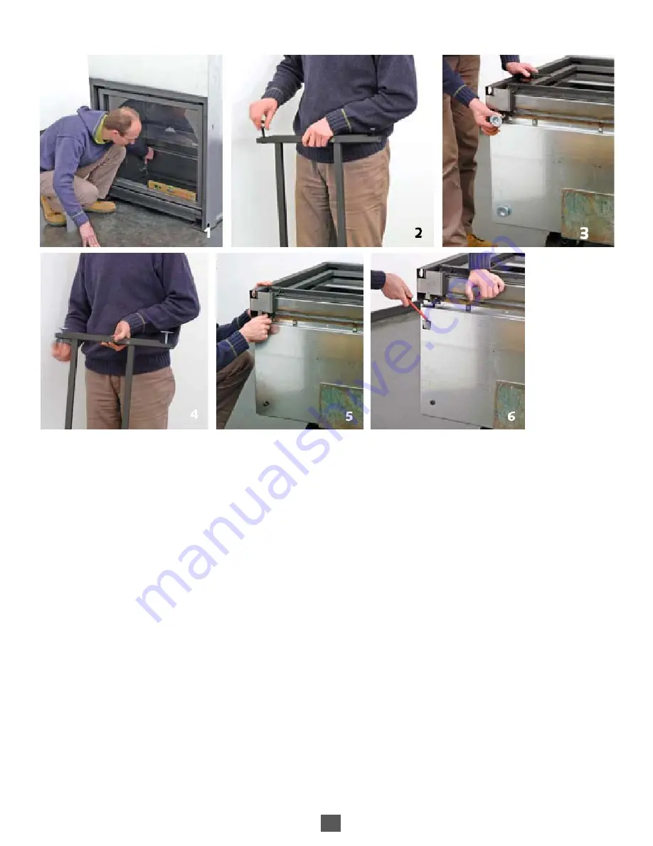
1. On cement boards or a masonry base:
Level the fireplace with the four adjustable struts, accessed
from inside the combustion chamber. Use a 5- mm Allen
key to adjust the height at the four corners (photo 1).
2. On the optional Stûv base:
Remove the two M10x40 screws (four in total) attached to
each leg (photo 2). Tilt the fireplace to lay it on its back,
then remove the adjustable struts located under the
fireplace (photo 3). Screw them onto the base for the full
length of the thread without tightening them (photo 4).
Caution: To prevent any unwanted air flow inside the
hearth, seal the threads that held the adjustable struts with
the extra M10x40 screws (photo 5). Remove the four caps
by prying them off (photo 6). If necessary, recut the base
elements so that the fireplace can be raised to the required
height. Insert these into the square holes (photo 7).
Because they are not symmetrical, the longer sides of the
base elements should be placed toward the front of the
fireplace. If these are not cut, they will raise the fireplace
17-1/2" with the hearth opening at 23-3/4" above floor
level (photo 9).
Le foyer sera posé soit :
– sur deux épaisseurs de fibro-ciment 1/2".
– sur un socle maçonné,
– sur un podium ajustable Stûv (fourni en option).
1. sur les panneaux de fibro-ciment ou sur un socle
maçonné :
Placer le foyer de niveau grâce aux 4 pieds à rotule
réglables en hauteur depuis l’intérieur de la chambre de
combustion. Utiliser la clé Allen de 5mm pour le réglage de
la hauteur des 4 coins (photo 1).
2. sur un podium Stûv (option) :
Retirer les 2 vis M10 X 40 fixées sur chaque pied (4 au
total) (photo 2). Coucher le foyer sur son dos, retirer les
pieds à rotule réglables (photo 3). Revisser complètement
les pieds à rotule (sans les bloquer) sur le podium (photo 4).
Attention : Pour éviter une circulation d’air parasite dans le
foyer, revisser les vis M10 X 40 dans les trous où étaient les
pieds à rotule réglables (photo 5).
Retirer les 4 opercules en faisant levier (photo 6). Recouper
éventuellement les éléments de piétement de sorte que le
foyer soit surélevé de la hauteur voulue ; les introduire dans
les trous carrés dégagés (photo 7).
Les piètements ne sont pas symétriques, placer les grands
côtés vers l’avant du foyer.
Sans recoupe, ils rehaussent le foyer de 44,3 cm ;
l’ouverture du foyer se trouve alors à 60 cm du sol (photo
9).
Summary of Contents for 21/135 SF
Page 1: ...21 85SF ...
Page 2: ...2 ...
Page 6: ...6 DIMENSIONS DIMENSIONS ...
Page 7: ...7 EXPLODED VIEW VUE EXPLOSÉE ...
Page 10: ...10 PLACEMENT INSERTION DE L UNITÉ ...
Page 13: ...13 INSTALLATION INSTALLATION ...
Page 15: ...15 TOP INSULATION ISOLATION DE DESSUS ...
Page 17: ...17 CONVECTION CONVECTION ...
Page 18: ...18 HEARTH EXTENSION EXTENSION DE L ÂTRE ...
Page 20: ...20 COMBUSTIBLE SHELF TABLETTE EN MATÉRIAU COMBUSTIBLE ...
Page 21: ...21 ...
Page 29: ...29 ...
Page 31: ...31 ...
Page 42: ...42 ...
Page 43: ...43 ...
Page 60: ...60 ...
Page 63: ...63 ...


