27
Rotation stop
The rotation stop enables you to choose a maximum rotation
angle to which the stove can turn.
> First of all, choose your configuration for the stove (see
previous pages). This will define your maximum rotation
angle.
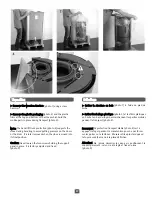
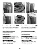
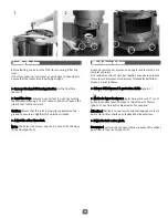
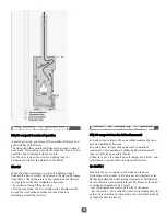
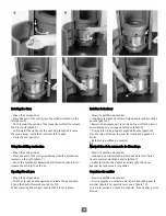
> Take out the 3 stepped screws with a flat screwdriver (2
screws at the front, 1 screw at the back) [photos 1 and 2].
Caution: Once the 3 stepped screws have been removed, do
not under any circumstances move or tilt the stove. This risks
damaging the rotation axle of the stove.
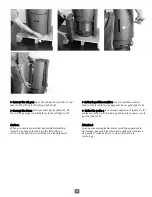
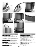
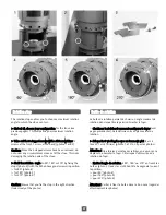
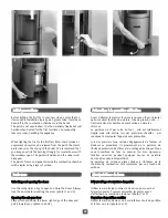
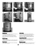
> Limit the rotation angle to 90°, 180° or 270° by fixing the
stops [photo 3] (with the M5x6 hexagonal screws) in position:
> for 90° [photo 4]
> for 180° [photo 5]
> for 270° [photo 6]
Caution: Ensure that you fix the stop in the right direction
(look closely at the photos).
Butée de rotation
La butée de rotation permet de choisir un angle maximal de
rotation dans lequel il sera permis d'orienter le foyer.
> Choisissez tout d'abord comment configurer le foyer (voir
pages précédentes). Cela définira votre angle maximal de
rotation.
> Enlever les 3 vis étagées avec un tournevis plat (2 vis à
l'avant, 1 vis à l'arrière) [photos 1 et 2].on a pas les photos!
Attention ! Une fois les 3 vis étagées retirées, en aucun cas ne
déplacer ou basculer le foyer. Cela risque d'abîmer l'axe de
rotation du foyer.
> Limiter l'angle de rotation à 90°, 180° ou 270° en fixant les
butées [photo 3] (avec les vis M5x6 tête hexagonale) suivant
la position:
> pour 90° [photo 4]
> pour 180° [photo 5]
> pour 270° [photo 6]
Attention! Veiller à fixer la butée dans le bon sens (regarder
attentivement les photos).
Summary of Contents for 30 Compact
Page 1: ...30 0 CO OMPAC CT ...
Page 2: ...2 ...
Page 8: ...8 ...
Page 9: ...9 30 COMPACT ...
Page 14: ...14 ...
Page 15: ...15 30 COMPACT ...
Page 31: ...31 30 COMPACT ...
Page 47: ...47 ...
Page 57: ...57 ...
Page 63: ...63 ...


