8
8
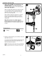
Hardware Used
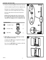
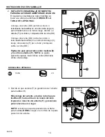
8. Place the small end cap (BB) onto the 3/4 in. tube (A).
Insert the transition ring (EE) into the straight tube (B).
Slide the 3/4 in. tube (A) through the transition
ring (EE) and into the straight tube (B), as shown.
Place the tape strips (GG) around the seams of
the tubes.
NOTE: After inserting the 3/4 in. tube (A) into
the straight tube (B) ensure that the transition
ring (EE) fits snuggly over the straight tube (B).
Transition Ring
x 1
EE
Small End Cap
x 1
BB
B
BB
EE
GG
Tape Strip
x 1
A
B
A
B
C
GG
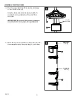
9.
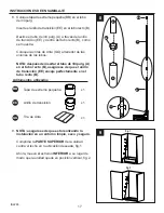
NOTE: Make sure you are installing in a clean,
dry and safe environment.
Compress the
TOP
of the unit against the ceiling in
the desired location,
fig 1.
Now, move the
BOTTOM
end into place so that the
unit is in a vertical position,
fig 2.
9
fig. 1
fig. 2
ASSEMBLY INSTRUCTIONS
IS2265


