background image

6

Lowes.com

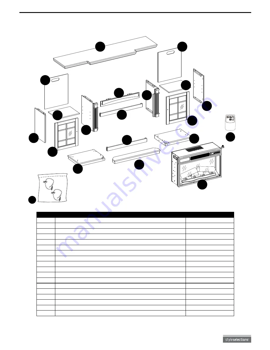
PACKAGE CONTENTS

PART

DESCRIPTION

QUANTITY

A

Front Base

1

B

Left Side Panel

1

C

Right Side Panel

1

D

Center Front Panel

1

E

Left Door

1

F

Right Door

1

G

Mantel Top

1

H

Wood Shelf

2

I

Left Partition

1

J

Right Partition

1

K

Insert Support Bar

1

L

Left Base

1

M

Right Base

1

N

Lower Insert Support Bar

1

O

Rear Panel

2

P

Insert

1

Q

Remote

1

R

Tipping Restraint Hardware Pack

1

J

F

C

B

A

D

G

L

P

O

O

M

E

H

H

I

K

N

Q

R

Summary of Contents for 26MM20243-C278

Page 1: ...TH MEDIA MANTEL Français p 18 Español p 35 Style Selections is a registered trademark of LF LLC All rights reserved EB15195 Questions problems missing parts Before returning to your retailer call our customer service department at 1 877 888 8225 8 a m 8 p m EST Monday Friday ...

Page 2: ... 60 Hz AMPS 12 5 Amps WATTS 1 500 Watts Product Specifications 2 Safety Information 3 Package Contents 6 Hardware Contents 7 Preparation 8 Assembly Instructions 8 Operating Instructions 13 Care and Maintenance 14 Troubleshooting 15 Warranty 16 Replacement Parts List 17 ...

Page 3: ... or personal injury Do not insert or allow foreign objects to enter any ventilation or exhaust opening as this may cause an electrical shock or fire or damage the appliance CAUTION High temperatures may be generated under certain abnormal conditions Do not partially or fully cover or obstruct the front of this heater If the supply cord is damaged it must be replaced by the manufacturer its service...

Page 4: ... used by children or persons with reduced physical sensory or mental capabilities or lack of experience and knowledge unless they have been given supervision or instruction 5 Always unplug this appliance when not in use 6 Do not operate any heater with a damaged cord or plug or after the appliance malfunctions or if it has been dropped or damaged in any manner 7 If the supply cord is damaged it mu...

Page 5: ...device complies with Part 15 of the FCC Rules Operation is subject to the following two conditions 1 This device may not cause harmful interference and 2 this device must accept any interference received including interference that may cause undesired operation Modifications not approved by the party responsible for compliance could void user s authority to operate the equipment This Class B digit...

Page 6: ... Center Front Panel 1 E Left Door 1 F Right Door 1 G Mantel Top 1 H Wood Shelf 2 I Left Partition 1 J Right Partition 1 K Insert Support Bar 1 L Left Base 1 M Right Base 1 N Lower Insert Support Bar 1 O Rear Panel 2 P Insert 1 Q Remote 1 R Tipping Restraint Hardware Pack 1 J F C B A D G L P O O M E H H I K N Q R ...

Page 7: ...rew Washer Shelf Pin Wood Dowel Door Pull Not to scale Touch up Pen Not to scale Screw Catch Screw Magnetic Spring Catch Not to scale Hinge Not to scale Qty 28 Qty 28 Qty 28 Qty 8 Qty 16 Qty 2 Qty 16 Qty 4 Qty 2 Qty 4 Qty 1 AA DD BB EE CC FF HH II JJ KK GG W 3 3 4 8 A ...

Page 8: ...knife 1 Push the left base L and right base M snug to the front base A and lower insert support bar N Secure using bolts AA and washers BB 2 Attach the magnetic spring catch HH to the left partition I and right partition J using catch screws II and tighten Hardware Used Hardware Used Hardware Used BB AA C B L A M N 1 2 3 Insert wood dowels CC into assembly where shown then attach left side panel B...

Page 9: ...ashers BB Then before proceeding to the next step go back with a Phillips screwdriver not included and ensure all connections are tight D G 4 5 DD O O 6 6 Attach the rear panels O to the back of the assembly using truss head screws DD through the pre drilled holes on the panels Hardware Used DD Truss Head Screw x 28 BB AA BB AA CC Hardware Used AA Bolt x 2 BB Washer x 2 Hardware Used AA CC Bolt Wo...

Page 10: ... FF Shelf Pin Door Pull x 8 x 2 8 Attach right door F to right side panel C through hinges JJ using screws GG Tighten with Phillips screwdriver Then remove the preassembled bolt from a door pull FF and install door pull FF to right door F using the bolt Repeat this step for left door E JJ GG GG 7 8 9 7 Attach the hinges JJ to the left door E and right door F using screws GG and tighten securely Ha...

Page 11: ... bolts AA and washers BB 11 Assembly is now complete With the help of another person move the unit to its final location and use the preassembled levelers as needed to ensure the unit s stability 10 11 K Hardware Used AA Bolt x 2 BB Washer x 2 WARNING Be sure to read all safety information prior to installing the insert P Insert P should be installed in the fireplace as close to the final position...

Page 12: ...he marked locations using 2 of the screws from the pack Attach the unit anchor to the mantel top G using the remaining 2 screws so it aligns with the wall anchor Then detach the cable of the anchor tether provided in the tipping restraint hardware pack R from the connection and thread the cable through the anchors Re attach the cable to the connection but do NOT tighten yet Repeat the above steps ...

Page 13: ... temperature setting The button on the control panel scrolls through specific temperature settings To change between Fahrenheit and Celsius press and hold the heater button on the control panel for 3 seconds Pressing the timer button will cycle through the timer settings 30 minutes 1 Hour 2H 3H 4H 5H 6H 7H 8H 9H and OFF HEATER TIMER ICON DESCRIPTION The heater can be operated by either the remote ...

Page 14: ...ing touch up pen KK For scratches stroke in direction of scratch For worn areas stroke in direction of wood grain Rub excess cororant promptly with a soft cloth No Bat Plea at a AAA 1 5V AAA 1 5V REPLACING THE BATTERIES When the remote Q stops operating or its range seems reduced it is time to replace the batteries Note Batteries should be removed if the product is to be left unused for a long tim...

Page 15: ...If so discontinue use of the heater and have a qualified electrician check and or replace the faulty outlet s Heater does not blow warm air Cool down cycle No action is required Cool down will continue to run for several minutes before shutting down Times will vary based on temperatures During this time cool air will blow No power logs do not glow No power to the unit Check that unit is plugged in...

Page 16: ... of same will not be covered by this warranty nor shall the manufacturer assume responsibility for same 6 The owner user assumes all other risks if any including the risk of any direct indirect or consequential loss or damage arising out of the use or inability to use the product except as provided by law 7 All other warranties expressed or implied with respect to the product its components and ac...

Page 17: ... PART DESCRIPTION PART NO 1 Flame Generator Drive Motor P10 6 Q 2 Thermostat Sensor INS NTC 3 Main Circuit Board Y15 C70 P15 4 Heater Blower Assembly Y15 C72 P01 5 Control Panel Circuit Board Y15 C70 P32 6 Control Panel Buttons Y15 C70 P85 7 Emberbed with Log Y15 S148 P02 8 Emberbed Circuit Board Y15 C75 P44E 9 Blue Flame Circuit Board Y15 C70 P40BL 10 Flame Circuit Board Y15 C76 P40 11 Spinner Y1...

Reviews: