Page 24
Component Access & Removal
WARMING DRAWER WWD30
4-7
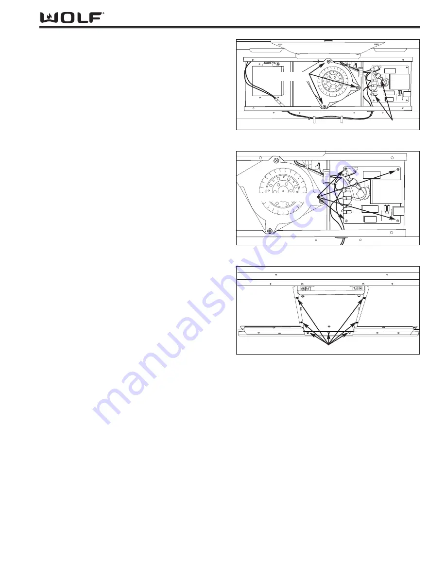
Figure 4-16. Power Board Removal
Power Board Removal
NOTE:
Electrical shock potential. Refer to warnings on
page 4-2.
The power board is located to the right of the fan
assembly on the outer back panel of unit. Four expand-
ing mandrels secure the power board to the outer back
panel.
NOTE:
You may want to mark the wire connectors to
ensure their proper location when reattaching to board.
To remove the power board, begin by removing the
drawer and cavity baffle from unit. Then, disconnect all
electrical leads from power board. With fingers, support
the corners of power board and pull board off of the
expanding mandrels.
Heating Element
NOTE:
Electrical shock potential. Refer to warnings on
page 4-2.
The heating element is mounted with two screws to a
bracket which is then secured to the element mounting
bracket with screws. The element mounting bracket is
then secured to the ceiling of the unit with four hex head
screws along the side flanges of the bracket, and three
hex head screws at the front of the unit cavity. These
three hex head screws pass through a small angle
bracket and a second bracket running the width of the
unit behind the drawer seals. Only the hex head screws
need to be removed to access the elem
ent. After remov-
ing the hex head screws, push the element bracket
twards the rear of the unit. Once the front of the element
bracket clears the front frame of the unit, drop the front
of the element bracket down and pull forward.
To remove the heating element, begin by removing the
drawer from unit. Next remove the cavity baffle.
Extract the seven hex head screws that
secure the heating element bracket to the ceiling.
Push bracket twards rear to release
front from frame.
NOTE:
Screws that need to be removed will be 1/4” hex
head.
Once you have access to the element and wiring you
can cut the electrical leads and remove the element
from the bracket.
Disconnect the remaining element wiring from the power
board and remove.
NOTE:
When installing new element, mount element to
mounting bracket first, then feed wires through grommet
and connect to power board.
NOTE:
Once bracket and element are reattached, pull
any remaining wire into power board location to avoid
interference with fan operation.
Expanding Mandrels
Figure 4-17. Heating Element Bracket Removal
(As Viewed from Inside Rear looking forward)
Remove Hex Head Screws
Figure 4-15. Fan Assembly Removal
Remove Screws
Electrical Leads


