
background image

FORESTER NA. (E)

11

Specifications

Specifications

11-2

. . . . . . . . . . . . . . . . . . . . . . . . . . . . . . . . . . . . . . . . . . . . . . . . . . . . . . . . . . . . . . 
Dimensions

11-2

. . . . . . . . . . . . . . . . . . . . . . . . . . . . . . . . . . . . . . . . . . . . . . . . . . . . . . . . . . . . . . . 
Engine

11-2

. . . . . . . . . . . . . . . . . . . . . . . . . . . . . . . . . . . . . . . . . . . . . . . . . . . . . . . . . . . . . . . . . . . . . 

Electrical system

11-2

. . . . . . . . . . . . . . . . . . . . . . . . . . . . . . . . . . . . . . . . . . . . . . . . . . . . . . . . 

Capacities

11-2

. . . . . . . . . . . . . . . . . . . . . . . . . . . . . . . . . . . . . . . . . . . . . . . . . . . . . . . . . . . . . . . . . 

Tires

11-3

. . . . . . . . . . . . . . . . . . . . . . . . . . . . . . . . . . . . . . . . . . . . . . . . . . . . . . . . . . . . . . . . . . . . . . . . 

Wheel alignment

11-3

. . . . . . . . . . . . . . . . . . . . . . . . . . . . . . . . . . . . . . . . . . . . . . . . . . . . . . . . . 

Fuses and circuits

11-4

. . . . . . . . . . . . . . . . . . . . . . . . . . . . . . . . . . . . . . . . . . . . . . . . . . . . . . . . 

Fuse panel located behind the coin tray

11-4

. . . . . . . . . . . . . . . . . . . . . . . . . . . . 

Fuse panel located in the engine compartment

11-6

. . . . . . . . . . . . . . . . . . . 

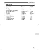
Bulb chart

11-7

. . . . . . . . . . . . . . . . . . . . . . . . . . . . . . . . . . . . . . . . . . . . . . . . . . . . . . . . . . . . . . . . . . . 

Vehicle identification

11-8

. . . . . . . . . . . . . . . . . . . . . . . . . . . . . . . . . . . . . . . . . . . . . . . . . . . . 

Summary of Contents for 1998 Forester

Page 1: ...Wear Seat Belts at All Times for Your Own Safety 1 9 9 8 O W N E R S M A N U A L ...

Page 2: ...tact the dealer from whom you purchased your SUBARU or the nearest SUBARU dealer The information specifications and illustrations found in this manu al are those in effect at the time of printing FUJI HEAVY INDUS TRIES LTD reserves the right to change specifications and designs at any time without prior notice and without incurring any obligation to make the same or similar changes on vehicles pre...

Page 3: ...nformation including details of coverage and exclusions is in the Warranty and Maintenance Booklet Please read these warranties carefully J Warranties for Canada All SUBARU vehicles distributed by Subaru Canada Inc and sold at re tail by an authorized SUBARU dealer in Canada come with the following warranties D SUBARU Limited Warranty D Anti Corrosion Warranty D Emission Control Warranty All warra...

Page 4: ... belt and contains precautions for the SRS AIRBAG Chapter 3 Instruments and controls This chapter informs you about the operation of instrument panel indica tors and how to use the instruments and other switches Chapter 4 Climate Control This chapter informs you how to operate the climate control Chapter 5 Audio This chapter informs you how to operate your audio system Chapter 6 Interior equipment...

Page 5: ...umber of WARNINGs CAUTIONs and NOTEs in this manual These safety warnings alert you to potential hazards that could result in injury to you or others Please read these safety warnings as well as all other portions of this manual carefully in order to gain a better understanding of how to use your SUBARU vehicle safely WARNING A WARNING indicates a situation in which serious injury or death could r...

Page 6: ...protection in the event of an accident the driver and all passengers in the vehicle should always wear seat belts when the vehicle is moving The SRS Supplemental Restraint System AIRBAG does not do away with the need to fasten seat belts In combination with the seat belts it offers the best combined protection in case of a serious accident Not wearing a seat belt increases the chance of severe inj...

Page 7: ...ants and small children should always be placed in an infant or child restraint system in the REAR seat which is appropriate for the child s age height and weight If a child is too big for a child restraint system the child should sit in the REAR seat and be restrained using the seat belts According to accident statistics children are safer when properly restrained in the rear seating positions th...

Page 8: ...refully read the sections Child Restraint System SRS AIR BAG 3 point Type Seat Belts and 2 point Type Seat Belts in chapter 2 of this owner s manual for instructions and precautions concerning the child restraint system seat belt system and SRS AIRBAG system ENGINE EXHAUST GAS CARBON MONOXIDE WARNING D Never inhale engine exhaust gas Engine exhaust gas contains carbon monoxide a colorless and odor...

Page 9: ...self your pas sengers and others In addition if you are injured in the accident alcohol may increase the severity of that injury Please don t drink and drive Drunken driving is one of the most frequent causes of accidents Since alcohol affects all people differently you may have consumed too much alcohol to drive safely even if the level of alcohol in your blood is below the legal limit The safest...

Page 10: ...are addicted to those drugs DRIVING WHEN TIRED OR SLEEPY WARNING When you are tired or sleepy your reaction will be delayed and your perception judgment and attentiveness will be impaired If you drive when tired or sleepy your your passengers and other persons chances of being involved in a serious accident may in crease Please do not continue to drive but instead find a safe place to rest if you ...

Page 11: ...r sudden stop unrestrained pets or cages can be thrown around inside the vehicle and hurt you or your pas sengers Besides the pets can be hurt under these situations It is also for their own safety that pets should be properly restrained in your vehicle Restrain a pet with a special traveling harness which can be se cured to the rear seat with a seat belt or use a pet carrier which can be secured ...

Page 12: ...ontrols Climate control 2 3 4 Audio Interior equipment Starting and operating In case of emergency 5 6 7 8 Appearance care Maintenance and service Specifications Consumer information and Reporting safety defects 12 Index 13 9 10 11 1 xi CONTINUED Table of contents ...

Page 13: ...l and driving vii All wheel drive vehicles Driving tips for AWD vehicles 7 32 Aluminum wheels If equipped Maintenance 10 42 Aluminum wheels If equipped Cleaning 9 6 AM FM stereo radio with cassette player 5 4 RADIO OPERATION 5 4 CASSETTE PLAYER OPERATION 5 9 CLOCK FUNCTION 5 11 Antenna 5 2 Anti lock brake system 7 30 Ashtray If equipped 6 12 AT OIL TEMPerature warning light 3 12 Automatic transmis...

Page 14: ...m light Luggage area light 6 15 Car phones and driving viii Cassette player operation AM FM stereo radio with cassette player 5 9 Catalytic converter 7 8 Center console 6 4 Charge warning light 3 9 CHECK ENGINE warning light Malfunction indicator lamp 3 10 Child restraint system 2 22 Installing child restraint system in the 3 point type seatbelt seating position 2 25 Installing child restraint sys...

Page 15: ...Windshield 4 4 4 8 Defogging Rear window defogger 3 24 Defogging Outside mirror defogger 3 26 Differential gear oil Front AT vehicles Maintenance 10 23 Differential gear oil Rear AWD vehicles Maintenance 10 24 Dome light Interior light 6 13 Door locks 1 3 Child safety locks 1 7 Locking and unlocking from the inside 1 5 Locking and unlocking from the outside 1 3 Power door locking switches 1 6 Door...

Page 16: ...l leaks Maintenance 10 6 Exhaust gas Engine exhaust gas 7 7 Exterior care 9 2 Washing 9 2 Waxing and polishing 9 3 F Flat tires 8 6 Changing a flat tire 8 6 Tire changing tools 8 10 Fog light Bulb replacement 10 51 Fog light switch 3 18 Four wheel drive vehicles Driving tips for AWD vehicles 7 32 Front differential gear oil Automatic transmission Maintenance 10 23 Front seats 2 2 Fore and aft adju...

Page 17: ...d 10 21 Fluid Brake fluid 10 28 Fluid Clutch fluid 10 29 Fluid Power steering fluid 10 26 Fuses Replacing a fuse 10 43 Fuses and circuits 11 4 Fuse panel located in the engine compartment 11 6 Fuse panel located behind the coin tray 11 4 G Gauges 3 5 Fuel gauge 3 6 Odometer Trip meter 3 5 Speedometer 3 5 Tachometer 3 6 Temperature gauge 3 7 Gasoline Fuel requirement 7 3 Gas tank capacity Specifica...

Page 18: ...6 Defrosting or defogging the windshield 4 4 Heating and defrosting 4 5 Heating 4 6 Ventilation 4 7 AIR CONDITIONER OPERATION 4 8 Cooling or dehumidifying 4 8 Defrosting or defogging 4 8 OPERATING TIPS FOR HEATING AND AIR CONDITIONING 4 9 Head light Lighting switch 3 14 Head light Bulb replacement 10 50 Head light aiming Checking the headlight aim 10 46 Head restraint 2 5 High beam indicator 3 13 ...

Page 19: ...3 K Key interlock Key interlock release 7 13 Key reminder chime 7 13 Keys 1 2 Key number 1 2 Master submaster and valet key 1 2 L License plate light Bulb replacement 10 54 Light Interior light 6 13 Light control 3 14 Fog light switch 3 18 Illumination brightness control 3 17 Light switch 3 14 Parking light switch 3 18 Lock Door Lock 1 3 Lock Child safety locks 1 7 Lock Power door locking switches...

Page 20: ...e is running 10 4 Maintenance tools 6 20 Malfunction indicator lamp CHECK ENGINE warning light 3 10 Manual transmission 7 16 Driving tips 7 17 Maximum speeds 7 17 Shifting speed for fuel economy 7 17 Manual transmission oil Maintenance 10 20 Meter Combination meter 3 4 Fuel gauge 3 6 Odometer Tripmeter 3 5 Speedometer 3 5 Tachometer 3 6 Temperature gauge 3 7 Mirrors 3 25 Inside mirror 3 25 Outside...

Page 21: ...e 7 26 Parking tips 7 27 Parking light switch 3 18 Parking light Bulb replacement 10 52 Periodic inspections 7 10 Pets and driving ix Power door locking switches if equipped 1 6 Power socket Accessory power socket 6 9 Power steering 7 23 Power steering fluid Maintenance 10 26 Power windows 1 8 Power windows switch cluster Driver s side 1 9 Front passenger s switch 1 10 Rear passenger s switches 1 ...

Page 22: ...ke pad 10 38 Parking brake lining 10 39 Replacement of windshield wiper blades 10 33 Replacing bulbs 10 49 Fog light 10 51 Front turn signal parking light and front side marker light 10 52 Headlight 10 50 High mount stop light 10 56 Interior light spot light and luggage compartment 10 55 License plate light 10 54 Rear combination lights 10 53 Reporting safety defects 12 4 Roof rail Roof rack 1 16 ...

Page 23: ...belt warning light and chime 2 13 3 8 Selector lever automatic transmission 7 19 Shift lever Manual transmission 7 16 Shift lock release 7 21 Side marker light Bulb replacement 10 52 Snow tires Winter driving 7 39 Spark plugs Maintenance 10 18 Specifications 11 2 Capacities 11 2 Dimensions 11 2 Electrical system 11 2 Engine 11 2 Tires 11 3 Wheel alignment 11 3 Speedometer 3 5 Spotlight if equipped...

Page 24: ...tray 6 6 Dashboard storage compartment 6 5 Door storage compartment 6 5 Glove compartment 6 3 Storage tray Luggage floor storage tray 6 18 Sun visors 6 2 Vanity mirror if equipped 6 2 T Tachometer 3 6 Temperature gauge 3 7 Tips for using the brakes 7 28 ABS Anti Lock Brake System if equipped 7 30 Brake system 7 29 Braking tips 7 28 Disc brake pad wear warning indicators 7 30 Tilt steering wheel 7 ...

Page 25: ...g trailer 7 44 Trailer towing 7 44 Connecting a trailer 7 49 Maximum load limits 7 45 Trailer hitches 7 49 Trailer towing tips 7 52 Warranties and maintenance 7 44 Trip meter Odometer Tripmeter 3 5 Turn signal indicator lights 3 13 Turn signal lever 3 14 Turn signal light Bulb replacement Front 10 52 Turn signal light Bulb replacement Rear 10 53 V Vanity mirror 6 2 Vehicle identification 11 8 Vent...

Page 26: ...ght Fuel gauge 3 7 Oil pressure warning light 3 9 Seat belt warning light and chime 3 8 SRS AIRBAG warning light 3 8 Washing Exterior care 9 2 Waxing Exterior care 9 3 Windows 1 8 Power window 1 8 Windshield washer fluid 10 32 Windshield wiper and washer switch 3 21 Winter driving 7 36 Corrosion protection 7 41 Driving on snowy and icy roads 7 38 Operation during cold weather 7 36 Rocking the vehi...

Page 27: ...g lights 1 8 Power windows 1 8 Power window switch cluster driver s side 1 9 Front passenger s switches 1 10 Rear passenger s switches 1 11 Rear gate 1 12 To open and close the rear gate 1 12 Fuel filler door and cap 1 13 To open and close the fuel filler door 1 13 Fuel filler cap 1 14 Refueling 1 14 Engine hood 1 15 Roof rail 1 16 Roof rack When luggage is put on the slats of the roof cross bar k...

Page 28: ...tch D Doors D Rear gate D Glove compartment The valet key fits only the ignition switch and door locks You can keep the glove compartment locked when you leave your vehicle and valet key at a parking facility J Key number The key number is stamped on the metal plate attached to the key set Write down the key number and keep it in another safe place not in the vehicle This number is needed to make ...

Page 29: ...an unlocked door HS0012 Locking without the key HS0011 1 2 1 Press the lock lever 2 Close the door 1 2 Locking without the key 1 Push the power door locking switch rearward 2 Close the door To lock the door from the outside without the key press the end of the lock lever down on the door and then close the door To lock the door from the outside using the power door locking switch push the switch r...

Page 30: ... outside with the key turn the key toward the rear To unlock the door turn the key toward the front Pull the outside door handle to open an unlocked door HS0013 Locking without the key Front door Locking without the key Rear door HS0011 1 2 1 Press the lock lever 2 Close the door 1 2 1 Press the lock lever 2 Close the door while holding the handle up To lock the front door from the outside without...

Page 31: ...he vehicle before locking the doors from the outside without the key J Locking and unlocking from the inside HS0014 Unlock Lock Red mark Inside door handle To lock the door from the inside press the end of the lock lever down To unlock the door from the inside pull the front end of the lock lever The red mark on the lock lever appears when the door is unlocked Pull the inside door handle to open a...

Page 32: ...r door locking switches at the driver s side and the front passenger s side doors To lock the doors push the switch rearward To unlock the doors push the switch forward When you close the doors after you set the door locks the doors remain locked NOTE Make sure that you do not leave the key inside the vehicle before locking the doors from the outside using power door locking switches ...

Page 33: ...t if a child accidentally opened the door and fell out Each rear door has a child safety lock that prevents the doors from being opened even if the inside door handle is pulled When the child safety lock lever is in the lock position the door cannot be opened from inside regardless of the position of the inner door handle lock lever The door can only be opened from the outside ...

Page 34: ...anyone s fingers arms or head from being caught in the window D Always lock the passengers windows using the lock switch when children are riding in the vehicle D Before leaving the vehicle always remove the key from the ignition switch for safety if a child remains in the vehicle Failure to follow this procedure could result in injury to a child operating the power window The power windows operat...

Page 35: ...or windows can be controlled by the power window switch cluster at the driver side door B To open or close the driver s window AUTO switch This switch has two functions Push the switch down until it clicks and release it and the window will fully open To stop the window halfway pull the switch up lightly Push the switch down lightly and hold it The window will open as long as the switch is held Pu...

Page 36: ...switch When the lock switch is in the LOCK position the passengers windows cannot be opened or closed J Front passenger s switch HS0019 Close Open To open the window push the switch down and hold it until the window reaches the desired position To close the window pull the switch up and hold it until the window reaches the desired position When the lock switch on the power window switch cluster lo...

Page 37: ...l the window reaches the desired position To close the window push the switch up and hold it until the window reaches the desired position When the lock switch on the power window switch cluster located on the driver s side door is in the LOCK position the rear passengers win dows cannot be operated with the rear passengers switches ...

Page 38: ... lock the rear gate insert the key in the keyhole and turn it coun terclockwise If your vehicle is equipped with power door locking switches the rear gate can also be locked and unlocked through use of the power door locking switches Refer to Power Door Locking Switches section in this chapter To open the rear gate first unlock the rear gate lock then pull the outside handle up To close the rear g...

Page 39: ...ly Fuel may be under pressure and spray out of the fuel filler neck espe cially in hot weather which may cause injury CAUTION Never add any cleaning agents to the fuel tank The addition of a cleaning agent may cause damage to the fuel system For choosing the right fuel for your SUBARU refer to the Fuel Require ments section located in chapter 7 J To open and close the fuel filler door HS0022 To op...

Page 40: ...emove the cap To put the cap back on turn it clockwise until you hear a clicking noise Be certain not to catch the cap tether under the cap while tightening NOTE If the fuel filler cap is not tightened until it clicks or if the tether is caught under the cap the CHECK ENGINE warning light may come on Refer to the Warning and Indicator Lights section located in chapter 3 J Refueling After the fuel ...

Page 41: ... it is not it might fly open while the vehicle is moving blocking your view which may cause an accident and serious bodily injury HS0025 HS0026 HS0024 To open the hood 1 Pull the hood release knob under the instrument panel 2 Release the secondary hood release located under the front of the engine hood by moving the lever toward the left Lift up the hood release ...

Page 42: ...od release it from a slightly higher position Do not push the hood forcibly to close it It could deform the engine hood Roof rail CAUTION D For cargo carrying purposes the roof rail must be used to gether with a roof cross bar kit The roof rail must never be used alone to carry cargo Otherwise damage to the roof or paint or a dangerous road hazard due to loss of cargo could result D When using the...

Page 43: ...gage is put on the slats of the roof cross bar kit When the roof cross bar kit is used as roof rack make sure the total car rying capacity of the luggage on the slats of the roof cross bar kit does not exceed 100 lb 45 kg Overloading may cause damage to the roof and create a safety hazard Always evenly distribute the luggage and secure it with straps or nets J Installing carrying attachments on th...

Page 44: ...elt 2 15 Adjusting the front seat shoulder belt anchor height 2 16 2 point type seat belts lap only belts 2 17 Fastening the seat belt 2 18 Unfastening the belt 2 19 Seat belt safety tips 2 20 Infants or small children 2 20 Children 2 20 Expectant mothers 2 21 Maintenance 2 21 Child restraint systems 2 22 Installing child restraint systems in the 2 point type seat belt position Rear center seating...

Page 45: ...ous internal injury or death D Do not put cushions or any other materials between occupants and seatbacks or seat cushions If you do so the risk of sliding under the lap belt and of the lap belt sliding up over the abdomen will increase and both can result in serious internal injury or death D The SRS AIRBAGs deploy with considerable speed and force Occupants who are out of proper position when th...

Page 46: ...CHILD SEAT IN THE FRONT SEAT DOING SO RISKS SERIOUS INJURY OR DEATH TO THE CHILD BY PLACING THE CHILD S HEAD TOO CLOSE TO THE SRS AIRBAG According to accident statistics children are safer when properly restrained in the rear seating positions than in the front seating positions For instructions and precautions concerning child restraint sys tems see the Child Restraint System section in this chap...

Page 47: ...d aft adjustment HS0029 HS0028 Pull the lever upward and slide the seat to the desired position Then re lease the lever and move the seat back and forth to make sure that it is securely locked into place J Reclining the seatback Pull the reclining lever up and adjust the seatback to the desired posi tion Then release the lever and make sure the seatback is securely locked into place ...

Page 48: ...ont edge For rear edge Lower Raise Raise Lower Turn either dial to adjust the angle and height of the seat cushion to the desired position J Head restraint adjustment HS0031 To raise the head restraint pull it up To lower it push the head restraint down while depressing the release button on the top of the seatback ...

Page 49: ...t position for the head restraint is just above or level with the top of the ears J Lumbar support HS0032 Pull the lever forward or backward Pulling the lever forward will increase the amount of support for your lower back ...

Page 50: ...er to overheat D When cleaning the seat do not use benzine paint thinner or any similar materials The seat heater operates when the ignition switch is either in the ACC or ON position HS0034 HS0033 Indicator LO HI Heating element To turn on the seat heater push the LO or HI position on the switch as desired depending on the temperature LO Normal heating HI Rapid heating The indicator located on th...

Page 51: ...lly when the occupant of the rear seat is a child be sure to position the seatback upright Children are more likely to slide under the lap belt than adults if the seatback is reclined in a colli sion D Do not put cushions or any other materials between occupants and seatbacks or seat cushions If you do so the risk of sliding under the lap belt and of the lap belt sliding up over the abdomen will i...

Page 52: ...s moving CAUTION Metallic parts of the seat belt can become very hot in a vehicle that has been closed up in sunny weather they could burn an oc cupant Do not touch such hot parts J Reclining the seat back HS0035 Pull the release knob up and adjust the seatback to the desired position Then release the knob and make sure the seatback is securely locked into place ...

Page 53: ...position unlock the seatback by pulling the release knob and raise it until it locks into place and make sure that it is securely locked J Head rest adjustment HS0038 HS0037 To raise the head rest pull it up To lower it push the head rest down while depressing the release button on the top of the seatback To move the head rest forward pull the top of the head rest forward To move the head rest rea...

Page 54: ...y D Keep the lap belt as low as possible on your hips In a colli sion this spreads the force of the lap belt over stronger hip bones instead of across the weaker abdomen D Seat belts provide maximum restraint when the occupant sits well back and upright in the seat To reduce the risk of sliding un der the seat belt in a collision the seatbacks should be always used in the upright position while th...

Page 55: ...ren are lighter and weaker than adults their risk of being injured from deploy ment is greater For that reason we strongly recommend that ALL children including those in child seats and those that have outgrown child restraint devices sit in the REAR seat properly restrained at all times in a child restraint device or in a seat belt whichever is appropriate for the child s age height and weight Be...

Page 56: ...hat has been closed up in sunny weather they could burn an oc cupant Do not touch such hot parts J Seat belt warning light and chime HS0039 Your vehicle is equipped with a seat belt warning device at the driver s seat This device causes the seat belt warning light on the instrument panel to light up for about six seconds when the ignition switch is turned to the ON position to remind the driver to...

Page 57: ...over to the Automatic Lock ing Retractor ALR mode When the child restraint system is removed make sure that the retractor operates as an Emergency Locking Retractor ELR For instructions on how to convert the retractor to the ALR mode and re store it to the ELR mode see the Child Restraint System section in this chapter J Fastening the seat belt CAUTION Metallic parts of the seat belt can become ve...

Page 58: ...t out more slowly 4 Insert the tongue plate into the buckle until you hear a click For the driver s side seat belt a seat belt warning device is provided if the driver is not wearing the seat belt with the ignition in the ON posi tion the warning light on the instrument panel comes on and a warning chime also sounds to remind the driver to wear the seat belt Refer to Warning and Indicator Lights s...

Page 59: ...k may result in neck injury during sudden brak ing or in a collision HS0040 Push The shoulder belt anchor height should be adjusted to the position best for you To lower the anchor height push the release button and slide down To raise the anchor height slide it up Pull down on the anchor to make sure that it is locked in place Always adjust the anchor height to the desired position so that the sh...

Page 60: ...le the vehicle is running If the seatbacks are not used in the upright position in a collision the risk of sliding under the lap belt and of the lap belt sliding up over the abdomen will increase and both can result in serious in ternal injury or death Especially when the occupant of the rear seat is a child be sure to position the seatback upright Children are more likely to slide un der the lap ...

Page 61: ...t adjust both seatbacks to the upright posi tion 2 Sit well back in the seat and pick up the tongue plate marked CEN TER Be careful not to twist the belt 3 Insert the tongue plate into the buckle marked CENTER until you hear a click The tongue plate marked CENTER can be fastened only into the buckle marked CENTER If the belt is not long enough for you hold the tongue plate at a right angle to the ...

Page 62: ...RBAG 2 19 CONTINUED J Unfastening the belt OM H0050 Push Push the button on the buckle NOTE When the seat belt is not in use store the seat belt in the seat belt pock et to prevent it from being damaged HS0041 Seat belt pocket ...

Page 63: ... obvious J Infants or small children Use a child restraint system that is suitable for your vehicle See informa tion on Child Restraint System in this chapter J Children If a child is too big for a child restraint system the child should sit in the rear seat and be restrained using the seat belts According to accident statistics children are safer when properly restrained in the rear seating posit...

Page 64: ... of polishes oils chemicals and particularly battery acid D Never attempt to make modifications or changes that will pre vent the seat belt from operating properly To clean the seat belts use a mild soap and lukewarm water Never bleach or dye the belts because this could seriously affect their strength Inspect the seat belts and attachments including the webbing and all hardware periodically for c...

Page 65: ...trained Because children are lighter and weaker than adults their risk of being injured from deploy ment is greater For that reason be sure to secure ALL types of child restraint devices including forward facing child seats in the REAR seats at all times You should choose a restraint device which is appropriate for the child s age height and weight According to accident statistics children are saf...

Page 66: ...up in sunny weather they could burn a small child Check the child restraint system before you place a child in it D Do not leave an unsecured child restraint system in your vehi cle Unsecured child restraint systems can be thrown around in side of the vehicle in a sudden stop turn or accident it can strike and injure vehicle occupants as well as result in serious injuries or death to the child Inf...

Page 67: ...s require that infants and small children be restrained in an approved child restraint system at all times while the vehicle is moving J Installing child restraint systems in the 2 point type seat belt position Rear center seating position HS0043 1 Adjust both rear seatbacks to fit the child restraint system placing them as upright as possible Make sure that both seatbacks are at the same angle an...

Page 68: ...raint system in the seating position 3 Fasten the lap and shoulder belts to the child restraint system follow ing the instructions provided by its manufacturer 4 Take up the slack in the lap belt 5 Put the shoulder portion of the belt between the rear seatback and the child restraint system 6 Pull out the seat belt fully from the retractor to change the retractor over from the Emergency Locking Re...

Page 69: ...tch the hook onto the top strap anchor and tighten the top strap HS0045 J Top strap anchors CAUTION D Always use a genuine top strap anchor D Always remove the head rest when installing a child restraint system with a top strap either on the left seating position or right seating position Otherwise it may happen that the top strap can not be fastened tightly B Installation point HS0046 For center ...

Page 70: ... assembled as shown in the illustration above 2 Remove the cover from the anchor installation point 3 Set the anchor at the desired installation point and tighten the bolt until the anchor is firmly secured 4 Install the anchor plate cover Please contact your SUBARU dealer about any questions you may have regarding the installation of the top strap anchor B Top strap anchor installation for U S mo...

Page 71: ... seat belt sys tem see the sections 3 point Type Seat Belts and 2 point Type Seat Belts in this chapter D Do not sit or lean unnecessarily close to the SRS AIRBAG The SRS AIRBAG deploys with considerable speed faster than the blink of an eye and force to protect in high speed collisions However the force of an SRS AIRBAG can injure an occupant whose body is too close to SRS AIRBAG It is also impor...

Page 72: ...ly restrained at all times The SRS AIRBAG deploys with considerable speed and force and can injure or even kill children especially if they are 12 years of age and under and are not re strained or improperly restrained Because children are lighter and weaker than adults their risk of being injured from deploy ment is greater For that reason we strongly recommend that ALL children including those i...

Page 73: ...BAG D Never allow a child to stand up or to kneel on the front pas senger s seat or never hold a child on your lap or in your arms The SRS AIRBAG deploys with considerable force and can injure or even kill the child HS0042 HS0227 Put children in the REAR seat prop erly restrained at all times Never install rearward facing child seat in the front passenger s seat HS0229 HS0228 Never allow a child t...

Page 74: ...e SRS AIRBAG supplements the seat belt by reducing the impact on the driver s and front passenger s head and chest The SRS AIRBAG is designed to deploy in the event of an accident in volving a moderate to severe frontal or front angled collision It is basi cally not designed to deploy in lesser frontal impacts because the nec essary protection can be achieved by the seat belt alone Also it is basi...

Page 75: ...s some smoke will be released This smoke could cause breathing problems for people with a history of asthma or other breathing trouble If you or your pas sengers have breathing problems after SRS AIRBAG deploys get fresh air promptly D Do not touch the SRS AIRBAG system components around the steering wheel and dashboard with bare hands right after deploy ment Doing so can cause burns because the c...

Page 76: ...er s side SRS AIRBAGs deploy as soon as a collision occurs After deployment SRS AIRBAGs start to deflate immedi ately so that the driver s vision is not obstructed SRS AIRBAG module Driver s side SRS AIRBAG module Passenger s side SRS AIRBAG control module including impact sensors ...

Page 77: ...ting of the SRS AIRBAGs after deployment is shorter than the blink of eye Although it is highly unlikely that the SRS AIRBAG would activate in a non accident situation should it occur the bag will deflate quickly not obscuring vision and will not interfere with the driver s ability to maintain control of the vehicle When the SRS AIRBAG deploys a sudden fairly loud inflation noise will be heard and...

Page 78: ...ing on the level of accident forces involved HS0240 HS0239 HS0238 The vehicle strikes a tele phone pole or similar ob ject The vehicle slides under a truck s load bed The vehicle sustains an oblique offset frontal im pact B Examples of the types of accidents in which the SRS AIRBAG will basically not deploy The SRS AIRBAG is basically not designed to deploy if it is stuck from side or from behind ...

Page 79: ...BAG control module including impact sensors D AIRBAG module driver s side D AIRBAG module passenger s side D All related wiring In the event of a malfunction indicated by any of following the vehicle should be taken promptly to your nearest SUBARU dealer to have the system checked Unless checked and repaired the SRS AIRBAG will not function reliably D Flashing or flickering of the warning light D ...

Page 80: ... servicing of the SRS AIRBAG see your nearest SUBARU dealer CAUTION The SRS AIRBAG control module including the impact sensors is located under the center console If you need service or repair in those area or near the steering wheel and column we recom mend that you have an authorized SUBARU dealer perform the work To ensure its long term reliability the SRS AIRBAG must be inspected by a SUBARU d...

Page 81: ...ants D To avoid accidental actuation of the system or rendering the system inoperative which may result in serious injury no modifi cations should be made to any components or wiring of the SRS AIRBAG This includes the installation of custom steering wheels or additional trim material or badges over the pad section of the steering wheel Installation of additional electrical electronic equipment su...

Page 82: ...equipment brush bar winches snow plow skid plate etc other than SUBARU genuine accessory parts to the front end D Modification of the suspension system and front end struc ture D Installation of a tire of different size and construction from the original tire listed on the tire placard attached to the door jamb Always consult your SUBARU dealer if you want to install any accessory parts to your ve...

Page 83: ...unction indicator lamp 3 10 ABS warning light for vehicles with ABS 3 12 AT OIL TEMPerature warning light for AT vehicles 3 12 Door open warning lights 3 13 Front wheel drive warning light for AT vehicles 3 13 Turn signal indicator lights 3 13 High beam indicator 3 13 Hazard warning flasher 3 14 Light controls 3 14 Light switch 3 14 Illumination brightness control 3 17 Parking light switch 3 18 Fo...

Page 84: ...e mirror page 3 25 8 Cup holder page 6 6 9 Heater or air conditioner control page 4 3 Q SRS AIRBAG page 2 28 W Power window switch page 1 8 E Glove compartment page 6 3 R Audio page 5 4 T Accessory power socket page 6 9 Cigarette lighter page 6 11 Y Horn page 3 25 U Tilt steering page 7 23 I Fog light switch page 3 18 O Cruise control main switch page 7 24 P Hood lock release page 1 15 A Remote co...

Page 85: ... Rear window wiper and washer switch page 3 22 5 Windshield washer page 3 21 6 Mist page 3 21 7 Windshield wiper page 3 21 8 Wiper control page 3 19 9 Light control page 3 14 Q Illumination brightness control page 3 17 W Headlight ON OFF page 3 14 E Headlight flasher High Low beam change page 3 15 R Turn signal for lane change page 3 15 T Turn signal page 3 16 HS0006 1 2 3 6 5 4 7 8 9 E R T Q W ...

Page 86: ...ing light page 3 13 9 Temperature gauge page 3 7 Q CHECK ENGINE warning light Malfunction indicator lamp page 3 10 W Front wheel drive warning light page 3 13 E Charge warning light page 3 9 R Brake system warning lights page 3 9 T Oil pressure warning light page 3 9 Y Odometer Trip meter selection and trip meter reset knob page 3 5 U Odometer Trip meter page 3 5 I Seat belt warning light page 3 8...

Page 87: ...lays the odometer and trip meter when the ignition switch is in the ON position To change the mode indication briefly push the knob The odometer shows the total distance that the vehicle has been driven The trip meter shows the distance that the vehicle has been driven since you last set it to zero To set the trip meter to zero select the indication of the trip meter by ...

Page 88: ...he tachometer in the red zone In this range fuel injection will be cut by the engine control module to protect the engine from overrevving The en gine will resume running normally after the engine speed is re duced below the red zone The tachometer shows the engine speed in thousands of revolutions per minute J Fuel gauge HS0155 Low fuel warning light The fuel gauge shows approximately the amount ...

Page 89: ...NGINE warning light may come on Refer to the CHECK ENGINE Warning Light Malfunction Indicator Lamp section in this chapter J Temperature gauge CAUTION If the pointer exceeds the normal operating range safely stop the vehicle as soon as possible See In case of emergency in this manual HS0052 Normal operating range The temperature gauge shows engine coolant temperature when the ignition switch is in...

Page 90: ...g light Malfunction indicator lamp ABS warning light if equipped AT OIL TEMP warning light automatic transmission vehicles If any lights fail to come on it indicates a burned out bulb or a malfunc tion of the corresponding system Consult your authorized SUBARU dealer for repair J Seat belt warning light and chime When the ignition switch is turned to the ON position the seat belt warning light wil...

Page 91: ...BARU dealer immediately J Oil pressure warning light CAUTION Do not operate the engine with the oil pressure warning light on This may cause engine damage If this light comes on when the engine is running it may indicate that the engine oil pressure is low and the lubricating system is not working prop erly If the light comes on while driving or does not go out after the engine starts stop the eng...

Page 92: ...e system warning light should come on while driving with the parking brake fully released and with the ignition switch posi tioned in ON it could be an indication of leaking of brake fluid or worn brake pads Have your vehicle checked by a SUBARU dealer immediately J CHECK ENGINE warning light Malfunction indicator lamp CAUTION If the CHECK ENGINE light comes on while you are driving have your vehi...

Page 93: ...p and retighten it until it clicks Make sure nothing is interfering with the sealing of the cap Tightening the cap will not make the CHECK ENGINE warning light turn off immediately It may take several driving trips If the light does not go out take your vehicle to your authorized SUBARU dealer immediately B If the light is blinking If the light is blinking while driving an engine misfire condition...

Page 94: ...he ON position but goes out immediately remaining off D The warning light remains on after the engine has been started but it goes out when the vehicle speed reaches about 8 mph 12 km h D The warning light comes on during driving but it goes out immedi ately and remains off When the ABS warning light is on the ABS function shuts down how ever the conventional brake system continues to operate norm...

Page 95: ...he drive mechanism is switched to Front Wheel Drive for maintenance or similar purposes J Turn signal indicator lights These lights show the operation of the turn signal or lane change signal If the indicator lights do not blink or blink rapidly the turn signal bulb may be burned out Replace the bulb as soon as possible Refer to Re placing Bulbs section in Chapter 10 J High beam indicator This lig...

Page 96: ...e hazard warning flasher push the hazard warning button on the instrument panel To turn off the flasher push the button again NOTE When the hazard warning flasher is on the turn signals do not work Light controls J Light switch WARNING To prevent battery discharge resulting from accidentally leaving your lights on when your vehicle is parked the light switch oper ates only when the ignition switch...

Page 97: ...icense plate light are on second position Headlights position lights instrument panel illumination tail lights and license plate light are on B High low beam change dimmer To change from low beam to high beam push the turn signal lever forward When the headlights are on high beam the high beam indi cator light a on the instrument panel is also on To switch back to low beam pull the lever back to t...

Page 98: ...em for CANADA models WARNING The tail lights parking lights and side marker lights are not turned on by the daytime running light system The light switch must always be turned to the a position when it is dark out side The low beam headlights will automatically come on at reduced brightness when the engine has started under the following condi tions D The parking brake is fully released D The auto...

Page 99: ...ne change push the turn signal lever up or down slightly and hold it during lane change The turn signal indicator lights will flash in the direction of the turn or lane change The lever will return automatically to the neutral position when you release it J Illumination brightness control HS0057 Brighten Darken When the lighting switch is in the p or a position you can adjust brightness of the ins...

Page 100: ...ghts Front side marker lights Tail lights License plate lights To turn off push the front end of the parking light switch Avoid leaving these lights on for a long time because that will run down the battery J Fog light switch if equipped The fog lights operate only when the headlights are on low beam Push the fog light switch to turn the fog lights on Press the switch again to turn them off ...

Page 101: ...eeze on the windshield blocking your view CAUTION D Do not operate the washer continuously for more than ten se conds or when the washer fluid tank is empty This may cause overheating of the washer motor Check the washer fluid level fre quently such as at fuel stops D Do not operate the wipers when the windshield or rear window is dry This may scratch the glass damage the wiper blades and cause th...

Page 102: ... shield washer solution to prevent streaking and to remove accumula tions of road salt or road film Keep the windshield washer button depressed at least for 1 second so that washer solution will be sprinkled all over the windshield or rear window D Grease wax insects or other material on the windshield or the wiper blade results in jerky wiper operation and streaking on the glass If you cannot rem...

Page 103: ... LO HI Mist To turn the wipers on push the wiper control lever down Intermittent LO Low speed HI High speed To turn the wipers off return the lever to the OFF position B Mist for a single wipe For a single wipe of the wipers pull the lever toward you The wipers operate until you release the lever B Washer HS0061 ...

Page 104: ...f the wiper stops during operation because of ice or some oth er obstruction on the rear window the wiper motor could burn out even if the wiper switch is turned off If this occurs promptly stop the vehicle in a safe place turn the ignition switch to the LOCK position and clean the rear window to allow proper wiper operation D To prevent the washer motor from overheating avoid operat ing the washe...

Page 105: ...er to the OFF position B Washer To wash the rear window while the rear wiper is operating turn the knob on the end of the wiper control lever counterclockwise to the position The washer fluid sprays until you release the knob To wash the rear window when the rear wiper is not in use turn the knob on the end of the wiper control lever clockwise to the position The washer fluid sprays and the wiper ...

Page 106: ...on the defogger push the switch To turn it off push the switch again The indicator light located on the switch is on while the rear window de fogger is operating The defogger will automatically shut off after about 15 minutes If the win dow clears before this time push the switch to turn it off It also turns off when the ignition switch is turned to the ACC or LOCK position If defrosting or defogg...

Page 107: ...hat the inside and outside mirrors are properly adjusted before you start driving J Inside mirror HS0064 Tab The inside mirror has a day and night position Pull the tab at the bottom of the mirror toward you for the night position Push it away for the day position The night position reduces glare from headlights ...

Page 108: ... mirror Do not use the con vex mirror to judge the distances of vehicles behind you when changing lanes Use the inside mirror or glance backwards to determine the actual size and distance of objects that you view in the convex mirror HS0065 B Adjusting mirrors To adjust the mirrors by hand push where indicated by the arrows HS0066 ...

Page 109: ...he direction control switch to the direction you want to move the mirror 3 Return the selection switch to the neutral position to prevent unintentional operation The mirrors can also be adjusted manually B Outside mirror defogger if equipped CAUTION To prevent the battery from being discharged do not operate the defogger continuously longer than necessary The outside mirror defogger shares the swi...

Page 110: ...e defogger will automatically shut off after about 15 minutes If the mirror clears before this time push the switch to turn it off It also turns off when the ignition switch is turned to the ACC or LOCK position If defrosting or defogging is desired when you restart your vehicle you have to push the switch to turn it on again NOTE While the outside mirror defogger is operating the rear window defo...

Page 111: ...N 4 8 Cooling or dehumidifying 4 8 Defrosting or defogging 4 8 Operating tips for heater and air conditioner 4 9 Cleaning ventilator grille 4 9 Efficient cooling after parking in direct sunlight 4 9 Lubrication oil circulation in the refrigerant circuit 4 9 Checking air conditioning system before summer season 4 10 Cooling and dehumidifying in high humidity and low temperature weather condition 4 ...

Page 112: ... or right and left to adjust the air flow direction HS0070 Move the thumb wheel up and down or right and left to adjust the air flow direction Move the thumb wheel up and down or right and left to adjust the air flow direction Oepn Close Oepn Close ...

Page 113: ...t panel outlets and the foot out lets Air flows through the foot outlets and some through the wind shield defroster outlets Air flows through the windshield defroster outlets and foot out lets Air flows through the windshield defroster outlets J Temperature control dial This dial regulates the hot air flow from the heater over a range from the blue area to red area J Fan speed control lever The fa...

Page 114: ...The air conditioner operates only when the engine is running Push the air conditioner button while the fan is in operation to turn on the air conditioner The indicator light will come on Push it again to turn off the air conditioner HEATER OPERATION J Defrosting or defogging the windshield HS0073 HS0072 To direct warm air to the windshield and front door windows 1 Set the air inlet selection lever...

Page 115: ...defrosting HS0075 HS0074 To direct warm air toward the floor and the windshield 1 Set the air inlet selection lever to the position 2 Set the air outlet control dial to the position 3 Set the temperature control dial to the most comfortable level 4 Set the fan speed control lever to the desired speed Warm air also comes out from the right and left air outlets To stop warm air flow from these outle...

Page 116: ...e most comfortable level 4 Set the fan speed control lever to the desired speed Warm air also comes out from the right and left air outlets To stop warm air flow from these outlets turn the corresponding thumb wheel to the position J Bi level heating HS0079 HS0078 This setting allows you to direct air of different temperatures from the instrument panel and outlets The air from the foot outlets is ...

Page 117: ...e difference between the air from the instrument panel outlets and the air from the foot outlets J Ventilation WARNING Continued operaton in the position may fog up the win dows Switch to the position as soon as the outside dusty condituion clears HS0081 HS0080 To force outside air through the instrument panel outlets 1 Set the air inlet selection lever to the position 2 Set the air outlet control...

Page 118: ...e air inlet selection lever to the position 2 Set the air outlet control dial to the position 3 Push the air conditioner button on 4 Set the temperature control dial to the blue area 5 Set the fan speed control lever at the highest speed J Defrosting or defogging HS0073 HS0072 ON position To direct warm air to the windshield and front door windows 1 Set the air inlet selection lever to the positio...

Page 119: ...the radiator this area should be kept clean because cooling performance is impaired by any accumulation of in sects and leaves on the condenser J Efficient cooling after parking in direct sunlight After parking in direct sunlight drive with the windows open for a few min utes to allow outside air to circulate into the heated interior This results in quicker cooling by the air conditioner Keep the ...

Page 120: ...ully depressed Such as at rapid accelera tion or driving on a steep upgrade J Refrigerant for your climate control system Your air conditioner uses ozone friendly refrigerant HFC134a Therefore the method of adding changing or checking the refrigerant is different from the method for CFC12 freon Consult your SUBARU dealer for ser vice Repairs needed as a result of using the wrong refrigerant are no...

Page 121: ...efroster perfor mance J Replacement procedure HS0254 HS0253 Screws Old filter Cooling unit Filter cover and rubber seal 1 Remove the filter cover by removing the two 2 screws 2 Remove the old filter HS0256 HS0255 Filter cover Screws New filter Plastic tab Rubber seal Cooling unit 3 Insert a new filter with the plastic tab facing forward 4 Install rubber seal on the duct opening ...

Page 122: ...on the duct opening 5 Install the filter cover and secure with two 2 screws Caution label HS0257 Center pillar Change label 6 Fill out information on the small label supplied with the filter kit 7 Attach small and large labels on the lower part of the center pillar ...

Page 123: ...TUNING 5 7 Automatic tuning SCN 5 8 Selecting preset stations 5 8 How to preset stations 5 8 CASSETTE PLAYER OPERATION 5 9 Cassette slot 5 9 Tape travel indicators 5 9 Program switching buttons PROG 5 10 Fast forward button 5 10 Rewind button 5 10 Stop and eject button 5 10 Tape program sensor button TPS 5 10 Dolby NR button BNR 5 11 Metal tape button MTL 5 11 CLOCK FUNCTION 5 11 Display mode 5 11...

Page 124: ... the antenna before hand to prevent it from being damaged Cap HS0258 Antenna Wrench The antenna and the special wrench for mounting dismounting the antenna is stored in the luggage floor storage tray at the front side 1 Remove the plug from the antenna base 2 Remove the cap at the threaded portion of the antenna ...

Page 125: ...e that the antenna is already installed on the vehicle at the time of delivery In such a case make sure of the stor age location of the special wrench by inquiring it of the personnel of your dealer J FM reception Although FM is normally static free reception can be affected by the sur rounding area atmospheric conditions station strength and transmitter distance Buildings or other obstructions ma...

Page 126: ...h and volume control Tuning buttons Preset buttons FM AM selection switch DISP button Stereo indicator Press station number Frequency J Power switch and volume control ON VOL HS0087 HS0086 Volume control Power ON OFF When the volume level is set at the level 18 The same knob is used for both power on off and volume control The radio is turned on and off by pushing the knob and the volume is con tr...

Page 127: ...note control Fader control Volume balance control between front and rear speakers Balance control Volume balance control between right and left speakers To change control modes Each pushing the T B button changes control modes in the following sequence starting from volume control mode When the radio is powered on control mode is in the volume control B Bass control HG0086 Bass volume control indi...

Page 128: ...volume control indication HG0087 Select the Treble control mode by pressing the T B button In the treble control mode the display shows the indication as shown The treble control has total of 13 volume levels TR 6 for minimum 0 for middle TR 6 for maximum Choose desired treble volume level by turning the volume control knob The control function returns to vol ume control mode after about 5 seconds...

Page 129: ...lance control mode by pressing the T B button In the balance control mode the display shows the indication as shown The balance control has total of 25 settings L 12 for left side maxi mum and right side minimum 0 for neutral R 12 for left side mini mum and right side maximum Choose desired setting by turning the volume control knob The control function returns to volume control mode after about 5...

Page 130: ... may be preset J How to preset stations 1 Press the FM AM selection switch to select either FM or AM reception 2 Press the SCN button or tune the radio manually until the desired station frequency is displayed 3 Press one of the preset buttons for at least two seconds to store the frequency The frequency of the station will flash once on the display at this time If the button is pressed for less t...

Page 131: ...es back in their boxes immediately after use to protect them from dust and dirt and to prevent the tape from unwinding D Never expose cassettes to heat direct sunlight or moisture D Clean the tape head once or twice a month using a wet type clean ing cassette J Cassette slot Insert a cassette with the exposed tape side facing to the right After inserting playback starts J Tape travel indicators Th...

Page 132: ...J Stop and eject button When button is pressed play back stops and the cassette tape is ejected Before the ignition switch turn to the OFF position eject the tape from the player Always make certain that you remove the cassette tape J Tape program sensor button TPS Press TPS button during playback to return to the beginning of the cur rent selection or to skip to the beginning of the next selectio...

Page 133: ...stem manufactured under license from Dolby Laboratories Licensing Corporation Dolby and double D Symbol are trade marks of Dolby Laboratories Licensing Corporation J Metal tape button MTL Press the MTL button when playing a metal or CrO2 tape CLOCK FUNCTION The radio has a built in clock function that displays the time when the ignition switch is turned either to ACC or ON HG0094 DISP buttons Tuni...

Page 134: ...g the time 1 Turn the ignition switch to ACC or ON 2 To adjust hour Press the DISP button and the TUNING button indicated with together to advance the hours in one hour increments Keeping the buttons pressed advances the hours quickly 3 To adjust minute Press the DISP button and the TUNING button indicated together to advance the minutes in one minute increments Keeping the buttons pressed advance...

Page 135: ...8 Setting the clock 6 8 Accessory power socket 6 9 Front accessory power socket if equipped 6 10 Rear accessory power socket 6 10 Cigarette lighter if equipped 6 11 Ashtray if equipped 6 12 Front ashtray 6 12 Rear ashtray 6 12 Coat hook 6 13 Interior light 6 13 Spotlight 6 14 Luggage area light 6 15 Luggage cover if equipped 6 15 Using the cover 6 16 To remove the cover 6 16 To install the cover 6...

Page 136: ...0088 To block out glare swing down the visors To use the sun visor at a side window swing it down and move it sideways J Vanity mirror if equipped HS0089 To use the vanity mirror swing down the visor and open the cover ...

Page 137: ...t D Do not store spray cans containers with flammable or corro sive liquids or any other dangerous items in the storage compart ment J Glove compartment HS0090 Unlock Lock To open the glove compartment pull the handle To close it push the lid firmly upward To lock the glove compartment insert the master key and turn it clock wise To unlock it insert the masterkey and turn it counterclockwise ...

Page 138: ...lock release J Sunglasses storage compartment HS0093 HS0092 Push The sunglasses storage compartment can be used to store a pair of sun glasses or small items such as a garage door opener To open the compartment push the button and it will automatically open ...

Page 139: ... open the dashboard compartment push the button and pull up on the lid Be sure to close the compartment fully before driving J Door storage compartment HS0095 Push Each door is equipped with a door storage compartment To open the compartment push the button and pull up on the lid ...

Page 140: ...reduce the risk of injury in the event of a sudden stop or an accident D Do not pick up a cup from the cup holder or put a cup in the holder while you are driving as this may distract you and lead to an accident D Take care to avoid spills Beverages if hot might burn you or your passengers Spilled beverages may also damage upholstery carpets or audio equipment ...

Page 141: ...use a larger cup pull it out farther until it stops J Front passenger s cup holder HS0100 HS0099 The front passenger s cup holder is built in the lid of the center console To use the cup holder open the lid by sliding it forward and unfold the arm Adjust the opening area by sliding the lid forward or rearward to fit the cup When not in use fold the arm and close the lid ...

Page 142: ...ole To use the cup holder open the lid by pulling its upper edge Clock HS0103 The clock displays the time when the ignition switch is in the ACC or ON positions J Setting the clock To set the hour press the H button To set the minutes press the M button To reset the minutes to 00 with a radio time signal push the S button ...

Page 143: ...ectric appliance is either too loose or too tight for the accessory socket this can result in a poor contact or cause the plug to get stuck Only use plugs that fit properly in the accessory socket D Use of an electric appliance in the accessory socket for a long period of time while the engine is not running can cause battery discharge D Before driving your vehicle make sure that the plug and the ...

Page 144: ...ry socket if equipped HS0104 The front accessory socket is located on the lower part of the instrument panel J Rear accessory socket HS0105 The rear accessory socket is located on the right side of the luggage compartment ...

Page 145: ...heat D If the lighter is replaced it is best to use only a genuine SUBARU part The use of parts that are not SUBARU made may result in a short circuit and overheating D Avoid the use of plug in type accessories spot lights shav ers etc Such accessories may damage the socket HS0106 The cigarette lighter operates only when the ignition switch is in the ON and ACC position To use the cigarette lighte...

Page 146: ... after using it to help reduce residual smoke HS0108 HS0107 J Front ashtray To open the ashtray pull the lid out To remove the ashtray for cleaning open it and pull it out while pushing the inner plate down J Rear ashtray To open the ashtray pull the upper edge of the lid To remove the ashtray for cleaning open it and pull it out while pushing the inner plate down ...

Page 147: ... Never hang anything on the coat hook that might obstruct the driver s view And do not hang items on the coat hook that weight 1 kg 2 2 lb or more The coat hook is attached to the rear passenger s hand grip behind the driver HS0109 Interior light HS0110 ...

Page 148: ...ays on for a few seconds after all doors are closed OFF The light stays off When leaving your vehicle make sure the light is turned off to avoid bat tery discharge Spotlight HS0111 Switch To turn on the spotlight push the switch To turn it off push the switch again When leaving the vehicle make sure the light is turned off to avoid bat tery discharge ...

Page 149: ...ght is turned off to avoid bat tery discharge Luggage cover if equipped CAUTION Do not place anything on the extended cover Putting excessive weight on the extended cover can break it and an object on the cover could tumble forward in the event of a sudden stop or colli sion This could cause serious injury The luggage cover is provided for covering the luggage compartment and to protect its conten...

Page 150: ...nhook it from the catches and it will rewind automatically You should hold on to the cover and guide it back into the cover housing while it is rewinding J To remove the cover HS0114 Fastening strap 1 Rewind the cover 2 Remove the fastening straps of the cover from the pillows 3 To take it off the retainer lift it out 4 Store the cover housing in the luggage area ...

Page 151: ...ION The cargo anchorage eyelets are designed only for securing light luggage Never try to secure any luggage which weighs more than the load capacity of the anchorage eyelets The maximum load capacity is about 44 lb 20 kg per eyelet HS0115 The luggage compartment is equipped with four anchorage eyelets so that luggage can be secured with a luggage net or ropes When using the anchorage eyelets rais...

Page 152: ...n stops or an acci dent D Do not store spray cans containers with flammable or corro sive liquids or any other dangerous items in the storage tray HS0116 Left side storage tray Front side storage tray Right side storage tray Center storage tray There are four storage trays under the floor of the luggage compartment They can be used to store small items ...

Page 153: ...ent 6 19 CONTINUED J Front left and right side storage tray HS0118 HS0117 HS0119 To open the lid raise the cargo anchorage eyelets and pull the tab up The jack and jack handle are stored in the left side storage tray ...

Page 154: ...le up To keep the lid open hang the hook provided on the backside of the lid on the rear edge of the roof The spare tire is stored under the storage tray Maintenance tools OM H2443 Your vehicle is equipped with the following maintenance tools Screwdriver Wheel nut wrench ...

Page 155: ...7 10 Periodic inspections 7 10 Ignition switch 7 10 LOCK 7 11 ACC 7 12 ON 7 12 START 7 12 Key reminder chime 7 13 Key interlock release AT vehicles only 7 13 Starting the engine 7 13 Manual transmission vehicles 7 14 Automatic transmission vehicles 7 14 During cold weather below 4 F 20 C 7 15 Flooded engine 7 15 Stopping the engine 7 16 Manual transmission 7 16 Shifting speed for fuel economy 7 17...

Page 156: ...ear warning indicators 7 30 ABS Anti Lock Brake System if equipped 7 30 Driving tips for AWD vehicles 7 32 Off road driving 7 34 Winter driving 7 36 Operation during cold weather 7 36 Driving on snowy and icy roads 7 38 Snow tires 7 39 Tire chains 7 40 Rocking the vehicle 7 40 Corrosion protection 7 41 Loading your vehicle 7 41 Vehicle capacity weight 7 42 GVWR and GAWR 7 43 Trailer towing 7 44 Wa...

Page 157: ... an emergency The same break in procedures should be applied to an overhauled engine newly mounted engine or when brake pads or brake linings are replaced with new ones Fuel requirements J Fuel Octane Rating Your engine is designed to use only unleaded gasoline with an octane rating of 87 AKI or higher This octane rating is the average of the Re search Octane and Motor Octane numbers and is common...

Page 158: ...arranty Your use of gasoline with detergent additives will help prevent deposits from forming in your engine and fuel system This helps keep your en gine in tune and your emission control system working properly and is a way of doing your part for cleaner air If you continuously use a high quality fuel with the proper detergent and other additives you should never need to add any fuel system clean...

Page 159: ...he fuel system Do not use fuel con taining methanol EXCEPT under these conditions D If undesirable driveability problems are experienced and you sus pect they may be fuel related try a different brand of gasoline before seeking service at your SUBARU dealer D Fuel system damage or driveability problems which result from the use of improper fuel are not covered under the SUBARU Limited War ranty St...

Page 160: ...idle and 2 500 RPM The enhanced I M test also includes a pressure check to identify evaporative emissions leaks in the fuel system The U S EPA has EXEMPTED SUBARU Full Time All Wheel Drive AWD vehicles from the following performance warranty short tests D Loaded Test D Idle Test With Loaded Preconditioning State I M Programs should test affected SUBARU AWD models using any other EPA 91 approved pe...

Page 161: ...able then use the ventila tion fan to force fresh air into the vehicle D Always keep the front ventilator inlet grille free from snow leaves or other obstructions to ensure that the ventilation system always works properly D If at any time you suspect that exhaust fumes are entering the vehicle have the problem checked and corrected as soon as pos sible If you must drive under these conditions dri...

Page 162: ...duce HC CO and NOx in exhaust gases thus providing cleaner exhaust To avoid damage to the catalytic converter D Use only unleaded fuel Even a small amount of leaded fuel will dam age the catalytic converter D Never start the engine by pushing or pulling the vehicle D Avoid racing the engine D Never turn off the ignition switch while the vehicle is moving D Keep your engine tuned up If you feel the...

Page 163: ...conditioner only when necessary D Keep the front and rear wheels in proper alignment D Avoid carrying unnecessary luggage or cargo Preparing to drive You should perform the following checks and adjustments every day be fore you start driving 1 Check that all windows mirrors and lights are clean and unob structed 2 Check the appearance and condition of the tires Also check tires for proper inflatio...

Page 164: ...eriodic inspections To keep your vehicle in the best condition at all times always have the recommended maintenance services listed in the maintenance schedule in the warranty and maintenance booklet performed at the specified time or mileage intervals Ignition switch WARNING Never turn the ignition switch to LOCK while the vehicle is be ing driven or towed because that will lock the steering whee...

Page 165: ... ignition switch will lock the steering wheel when you remove the key If turning the key is difficult turn the steering wheel slightly to the right and left as you turn the key B Automatic transmission vehicles HS0124 HS0123 The key can be turned from ACC to LOCK only when the selector lever is in the P position ...

Page 166: ...accessory power sock et etc can be used J ON This is the normal operating position after the engine is started J START CAUTION Do not turn the ignition switch to the START position while the engine is running The engine is started in this position The starter cranks the engine to start it When the key is released after the engine has started the key automatically returns to the ON position ...

Page 167: ...le front Release lever 1 Take out the screwdriver from the tool bag 2 Remove three screws securing the undercover of the steering col umn 3 Remove the under cover of the steering column 4 Turn the ignition key while pressing the key interlock release lever Take your vehicle to the nearest SUBARU dealer immediately to have the key interlock system repaired Starting the engine CAUTION Do not operate...

Page 168: ...e and then turn the ignition switch to the START position again while depressing the ac celerator pedal half way down 6 Confirm that all warning and indicator lights have gone off after the engine has started The fuel injection system automatically lowers the idle speed as the engine warms up J Automatic transmission vehicles CAUTION If you restart the engine while the vehicle is moving shift the ...

Page 169: ...he engine warms up While the engine is warming up make sure that the selector lever is at the P or N position and that the parking brake is applied J During cold weather below 4 F 20 C If the engine is difficult to start using the normal method without de pressing the accelerator pedal turn the ignition switch to the START position while slightly depressing the accelerator pedal J Flooded engine I...

Page 170: ...o lock The ignition switch should be turned off only when the engine is idling Manual transmission CAUTION Shift into reverse ONLY when the vehicle has completely stopped It may cause damage to the transmission to try shifting into reverse when the vehicle is moving The manual transmission is a fully synchromeshed 5 forward and 1 re verse speed transmission HS0128 The shift pattern is shown on the...

Page 171: ...except for brief acceleration in an emergency J Driving tips Do not drive with your foot resting on the clutch pedal and do not use the clutch to hold your vehicle at standstill on an upgrade Either of those actions may cause clutch damage Do not drive with your hand resting on the shift lever This may cause wear on the transmission components When it is necessary to reduce vehicle speed due to sl...

Page 172: ...backward CAUTION D Shift into the P or R position only after the vehicle is com pletely stopped Shifting while the vehicle is moving may cause damage to the transmission D Do not race the engine for more than five seconds in any posi tion except the N or P position when the brake is set or the tires are on blocks This may cause the automatic transmission fluid to overheat The automatic transmissio...

Page 173: ...ely When you park the vehicle first set the parking brake fully then shift into the P position Do not hold the vehicle only with the transmis sion The shift interlock function is employed in this automatic transmission system to ensure safety of starting the vehicle To shift the selector lever from the P to the any other position you have to depress the brake pedal fully then push the release butt...

Page 174: ...d the acceleration you require When more acceleration is required in this position press the acceler ator pedal fully to the floor and hold that position The transmission will automatically downshift to 3rd 2nd or 1st gear When you release the pedal the transmission will return to the original gear position B 3 Third This position is for using engine braking when going down a hill or for climbing ...

Page 175: ...peeds Never drive with the tachometer needle in the critical engine speed range except for brief acceleration in an emergency J Driving tips D Always apply the foot or parking brake when the vehicle is stopped in the D 3 2 1 or R position D Always set the parking brake when parking your vehicle Do not hold the vehicle only with the transmission D Never shift into the D 3 2 or 1 position while back...

Page 176: ...nd of the selector lever cover HS0132 Shaft portion of the screwdriver 6 Draw the shaft portion of the screwdriver from the grip and then insert the shaft into the hole 7 Push down on the shaft while pushing the release button and move the selector lever from the P to the N position 8 Remove the shaft from the hole Depress the brake pedal and start the engine Take your vehicle to the nearest SUBAR...

Page 177: ...the seat position Refer to Front Seat section chapter 2 2 Pull the tilt lock lever down 3 Move the steering wheel to the desired level 4 Push the lever up to lock the steering wheel in place 5 Make sure that the steering wheel is securely locked by moving it up and down J Power steering CAUTION Do not hold the steering wheel at the fully locked position left or right for more than five seconds Thi...

Page 178: ...lippery or winding roads D driving in heavy traffic Cruise control enables you to maintain a constant vehicle speed without holding your foot on the accelerator pedal and it is operative when the vehicle speed is 25 mph 40 km h or more Make sure the main switch is turned OFF when the cruise control is not in use to avoid unintentional cruise setting J To set cruise control HS0136 Main switch Contr...

Page 179: ...ssion vehicles only To resume the cruise control after it has been temporarily canceled and with vehicle speed of 25 mph 40 km h or more push the control lever upward in the ACCEL RESUME direction to return to the original cruis ing speed automatically J To turn off the cruise control There are two ways to turn off the cruise control D Push the main switch again D Turn the ignition switch to the A...

Page 180: ... vehicle speed about 1 mph 1 6 km h Press the control lever repeatedly until the desired speed is reached OR 1 Depress the brake pedal to release cruise control temporarily 2 When the speed decreases to the desired speed press the control lever downward in the SET COAST direction once Now the desired speed is set and the vehicle will keep running at that speed without depressing the accelerator pe...

Page 181: ...NG D Never leave unattended children or pets in the vehicle They could accidentally injure themselves or others through inadver tent operation of the vehicle Also on hot or sunny days the tem perature in a closed vehicle could quickly become high enough to cause severe or possibly fatal injuries to them D Do not park the vehicle over flammable materials such as dry grass waste paper or rags as the...

Page 182: ...to hold the vehicle For better parking brake power depress the brake pedal firmly while set ting the parking brake HS0140 HS0139 When parking on a hill always turn the steering wheel When the vehicle is headed up the hill the front wheels should be turned away from the curb When facing downhill the front wheels should be turned into the curb Tips for using the brakes J Braking tips WARNING Never r...

Page 183: ...the vehicle Keep driving straight ahead while gradually reducing speed Then slowly pull off the road to a safe place J Brake system B Two separate circuits Your vehicle has two separate circuit brake systems Each circuit works diagonally across the vehicle If one circuit of the brake system should fail the other half of the system still works If one circuit fails the brake pedal will goes down muc...

Page 184: ...riving overconfidence because you are driving with an ABS equipped vehicle could easily lead to a serious accident CAUTION D When driving on badly surfaced roads gravel roads icy roads or over deep newly fallen snow stopping distances may be long er for a vehicle with the ABS system than one without When driv ing under these conditions therefore reduce your speed and leave ample distance from othe...

Page 185: ...d of ABS from the engine compartment just after the vehicle started These are caused by an automatic functional test of the ABS system being carried out and does not indicate any abnormal condi tion B ABS warning light HS0156 The ABS warning light comes on when the ignition switch is turned to the ON position and goes out after about two seconds This is an indication that the ABS system is working...

Page 186: ...t it goes out when the vehicle speed reaches about 8 mph 12 km h D The warning light comes on during driving but it goes out immedi ately and remains off When driving with an insufficient battery voltage such as when the en gine is jump started the ABS warning light may come on This is due to the low battery voltage and does not indicate a malfunction When the battery becomes fully charged the lig...

Page 187: ...s under snowy or slippery conditions than a two wheel drive vehicle There is little differ ence in handling however during extremely sharp turns or sudden brak ing Therefore when driving down a slope or turning corners be sure to reduce your speed and maintain an ample distance from other vehicles D When replacing a tire make sure you use only the same size construc tion brand and load range as th...

Page 188: ...passenger car and is neither a conventional off road vehicle nor an all terrain vehicle If you do take your Subaru off road cer tain common sense precautions such as the following should be taken D Make certain that you and all of your passengers are wearing seat belts D Carry some emergency equipment such as a towing rope or chain a shovel wheel blocks first aid kit and portable phone or citizens...

Page 189: ...on the brake pedal Repeat that process several times to dry out the brake discs and brake pads D Do not drive or park over or near flammable materials such as dry grass or fallen leaves as they may burn easily The exhaust system is very hot while engine is running and right after engine stops This could create a fire hazard D After driving through tall grass mud rock sand rivers etc check that the...

Page 190: ...schedule described in the Warranty and Maintenance Booklet Remember that damage done to your Subaru while operating if off road and not using common sense precautions such as those listed above is not eligible for warranty coverage Winter driving HS0141 J Operation during cold weather Carry some emergency equipment such as tire chains a window scrap er a bag of sand flares a small shovel and jumpe...

Page 191: ...ke pedal and all other controls operate smoothly Clear away ice and snow that has accumulated under the fenders to avoid making steering difficult During severe winter driving stop when and where it is safe to do so and check under the fenders peri odically B Parking in cold weather WARNING Snow can trap dangerous exhaust gases under your vehicle Keep snow clear of the exhaust pipe and from around...

Page 192: ...mpty If your SUBARU is not going to be used for an extended period it is best to have the fuel tank filled to capacity J Driving on snowy and icy roads WARNING Do not use the cruise control on slippery roads such as snowy or icy roads This may cause loss of vehicle control To prevent skidding and slipping avoid sudden braking abrupt accelera tion high speed driving and sharp turning when driving o...

Page 193: ...the windshield gets warmed enough to melt the fro zen snow on it wash it away using the windshield washer Snow stuck on the wiper arm prevents the wiper from working effec tively If snow is stuck on the wiper arm pull off the road to a safe place then remove it If you stop the car at road side use the hazard warning flasher to alert other drivers We recommend use of non freezing type wiper blades ...

Page 194: ...front wheels only Use only SAE class S type chains that are of the correct size for your tires so as not to damage the vehicle body or suspension When driving with tire chains drive at speeds below 19 mph 30 km h When a temporary spare tire is on a front wheel replace the temporary spare tire with the rear tire on the same side of the vehicle and then fit chains on the front tires Always use the u...

Page 195: ...sible D When you carry something inside the vehicle secure it when ever you can to prevent it from being thrown around inside the vehicle in sudden stop sharp turn or accident D Do not pile heavy loads on the roof These loads raise the vehicle s center of gravity and make it more prone to tip over D Secure skis and other lengthy items properly to prevent them from shooting forward and causing seri...

Page 196: ...the driver s side door jamb It includes the total weight of driver and all passengers and their belongings any optional equipment such as a trailer hitch roof rack or bike carrier etc and the tongue load of a trailer The tire information label also shows recommended tire inflation pressure under full loading and trailer towing conditions Adjust tire inflation pres sures according to the loading co...

Page 197: ...uding standard equipment fluids emergency tools and spare tire assembly plus the vehicle capac ity weight In addition the total weight applied to each axle GAW must never ex ceed the GVWR The front and rear GAWs can be adjusted by relocating luggage inside the vehicle Even if the total weight of your luggage is lower than the vehicle capacity weight either front or rear GAW may exceed the GAWR dep...

Page 198: ...ollow the instructions on correct installa tion and use provided by the trailer and other towing equipment manufacturers SUBARU assumes no responsibility for injuries or vehicle damage that result from trailer towing equipment or from any errors or omissions in the instructions accompanying such equipment or for your failure to fol low the proper instructions J Warranties and maintenance SUBARU wa...

Page 199: ...r total weight GVW GAWs and tongue load Make sure the load and its distribution in your vehicle and trailer are acceptable B Total trailer weight Model Conditions Maximum total trailer weight MT models When towing a trailer without brakes 1 000 lbs 453 kg When towing a trailer with brakes 2 000 lbs 906 kg AT models When towing a trailer without brakes 1 000 lbs 453 kg When towing a trailer with br...

Page 200: ...t of the vehicle driver passengers luggage trailer hitch trailer tongue load and any other optional equipment installed on your vehicle Therefore the GVW changes depending on the situation Determine the GVW each time before going on a trip by putting your vehicle and trailer on a vehicle scale GVWR is shown on the certification plate located on the driver s door jamb of your vehicle HS0143 Gross V...

Page 201: ...are within safe driving limits you should have your vehicle and trailer weighed at a commercial weighing station Be sure that all cargo is firmly secured to prevent a change in weight distribution while driving B Tongue load WARNING If the trailer is loaded with more weight in the back of trailer s axle than in the front the load on the rear axle of the towing vehicle is taken off This may cause t...

Page 202: ...5 Bathroom scale Jack The tongue load can be adjusted by proper distribution of the load in the trailer Never load the trailer with more weight in the back than in the front approximately 60 percent of the trailer load should be in the front and approximately 40 percent in the rear Also distribute the load as evenly as possible on both the left and right sides Be sure that all cargo is firmly secu...

Page 203: ...trailer towing equipment Choose a proper hitch for your vehicle and trailer The use of genuine SUBARU trailer hitch is recommended A genuine SUBARU hitches are available from your SUBARU dealer If use of a non genuine hitch is unavoidable be sure the hitch is suited to your vehicle and trailer Consult with a professional hitch supplier to assist you in choosing an appropriate hitch for your vehicl...

Page 204: ... hitch ball should break or become disconnected the trailer could get loose and create a traffic safety hazard For safety always connect the tow vehicle and trailer with trailer safety chains Pass the chains crossing each other under the trailer tongue to prevent the trailer from dropping onto the ground in case the trailer tongue should disconnect from the hitch ball Allow sufficient slack in the...

Page 205: ...nction of your vehicle s lighting system Connection of trailer lights to your vehicle s electrical system requires modifications to the vehicle s lighting circuit to increase its capacity and accommodate wiring changes To ensure the trailer lights are connected properly please consult your SUBARU dealer Check for proper operation of the turn signals and the brake lights each time you hitch up ...

Page 206: ...mploy extra caution when towing a trailer and you should never speed You should also keep the fol lowing tips in mind B Before starting out on a trip D Check that the vehicle and vehicle to hitch mounting are in good condition If any problems are apparent do not tow the trailer D Check that the vehicle sits horizontally with the trailer attached If the vehicle is tipped sharply up at the front and...

Page 207: ...r and release the clutch at moderate engine RPM D Avoid uneven steering sharp turns and rapid lane changes D Slow down before turning Make a longer than normal turning radius because the trailer wheels will be closer than the vehicle wheels to the inside of the turn In a tight turn the trailer could hit your vehicle D Crosswinds will adversely affect the handling of your vehicle and trailer causin...

Page 208: ...EMP warning light for AT vehicles since the engine and transmission are relatively prone to overheating under these conditions If the water temperature gauge needle approaches the OVERHEAT zone or the ATF OIL TEMP warning light illuminates immediately switch off the air conditioner and stop the vehicle at the nearest safe place Refer to Engine Over heat section chapter 8 and Warning and Indicator ...

Page 209: ...should take the following steps 1 Apply the brakes and hold the pedal down 2 Have someone place wheel blocks under both the vehicle and trailer wheels 3 When the wheel blocks are in place release the regular brakes slowly until the blocks absorb the load 4 Apply the regular brakes and then apply the parking brake slowly release the regular brakes 5 Shift into 1st or reverse gear manual transmissio...

Page 210: ...ing from the engine compartment 8 3 Jump starting 8 3 How to jump start 8 4 Flat tires 8 6 Changing a flat tire 8 6 Tire changing tools 8 10 Towing 8 12 Transporting your vehicle using a flat bed truck 8 12 Towing with the front wheels raised off the ground for AT vehicles only 8 12 Towing with all wheels on the ground 8 13 Towing eyelet 8 15 ...

Page 211: ...h Turn it off by pushing the switch again Engine overheating WARNING Never attempt to remove the radiator cap until the engine has been shut off and has fully cooled down When the engine is hot the coolant is under pressure Removing the cap while the engine is still hot could release a spray of boiling hot coolant which could burn you very seriously If the engine overheats safely pull off the road...

Page 212: ...reserve tank add coolant to the reserve tank Then remove the radiator cap and fill the radiator with coolant If you remove the radiator cap from a hot radiator first wrap a thick cloth around the radiator cap then turn the cap counterclockwise slowly with out pressing down until it stops Release the pressure from the radiator After the pressure has been fully released remove the cap by pressing do...

Page 213: ...eep your fingers hands clothing hair and tools away from the cooling fan belts and any other moving engine parts Removing rings watches and ties is advisable When your vehicle does not start due to a run down discharged bat tery the vehicle may be jump started by connecting your battery to another battery called the booster battery with jumper cables Jump starting is dangerous if it done incorrect...

Page 214: ...e other cable to the negative terminal of the booster battery 4 Connect the other end of the cable to the engine lifting bracket Make sure that the cables are not near any moving parts and that the cable clamps are not in contact with any other metal 5 Start the engine of the vehicle with the booster battery and run it at moderate speed Then start the engine of the vehicle that has the dis charged...

Page 215: ... tire while driving never brake suddenly keep driving straight ahead while gradually reducing speed Then slowly pull off the road to a safe place J Changing a flat tire WARNING D Do not use oil or grease on the wheel studs or nuts when the spare tire is installed This could cause the nuts to become loose and lead to an accident D Never place a tire or tire changing tools in the passenger compartme...

Page 216: ...5 Take out the spare tire jack and wheel nut wrench See Tire Chang ing Tools in this chapter 6 Loosen the wheel nuts using the wheel nut wrench but do not remove the nuts HS0149 7 Place the jack under the side sill at the front or rear jack up point clos est to the flat tire Turn the jackscrew by hand until the jack head engages firmly into the jack up point ...

Page 217: ...and turn the handle clock wise until the tire clears the ground Do not raise the vehicle higher than necessary HS0151 9 Remove the wheel nuts and the flat tire 10 Before putting the spare tire on clean the mounting surface of the wheel and hub with a cloth ...

Page 218: ...ightening order in the illustration HS0152 1 4 2 5 3 The torque for tightening the nuts is 58 to 72 ft lb 78 to 98 N m 8 to 10 kg m This torque is equivalent to applying about 88 to 110 lbs 40 to 50 kg at the top of the wheel nut wrench Never use your foot on the wheel nut wrench or a pipe extension on the wrench because you may exceed the specified torque Have the wheel nut torque checked at a ne...

Page 219: ...0 HS0153 Flat tire Attaching bolt Spacer Also store the jack and wheel nut wrench in their storage locations See Tire Changing Tools in this section J Tire changing tools HS0004 Spare tire Jack handle Jack ...

Page 220: ...the attaching bolt counterclockwise then take the spare tire out B Jack and jack handle HS0160 HS0118 The jack is stored under the left side of the luggage floor To take out the jack First raise the cargo anchorage eyelet on the rear left side of the lug gage compartment and pull the tab to open the lid turn the jack screw counterclockwise to loosen it then remove the jack The jack handle is store...

Page 221: ...or 1st for manual transmission vehicles 2 Pull up the parking brake lever firmly 3 Secure the vehicle onto the carrier properly with safety chains Each of safety chain should be equally tightened and care must be taken not to pull the chains so tightly that the suspension bottoms out J Towing with the front wheels raised off the ground for AT ve hicles only WARNING Never tow manual transmission AW...

Page 222: ...the ACC position while the vehicle is being towed 4 Take up slack in the towline slowly to prevent damage to the vehicle J Towing with all wheels on the ground WARNING D Never turn the ignition switch to the LOCK position while the vehicle is being towed because the steering wheel and the direc tion of the wheels will be locked D Remember that the brake booster and power steering do not function w...

Page 223: ... bed truck HS0163 We do not recommend this method of towing Use this method only when towing service by a SUBARU dealer or a commercial towing service is not available 1 Check the transmission and differential oil levels and add oil to bring it to the upper level if necessary 2 Release the parking brake and put the transmission in neutral 3 The ignition switch should be in the ACC position while t...

Page 224: ...e muffler under the vehicle for towing purposes D Do not apply excessive lateral load to the towing eyelets HS0165 HS0164 Towing eyelet Towing eyelet HS0166 Never use tie down eyelet for towing purpose The towing eyelets should be used only in an emergency e g to free a stuck vehicle from mud sand or snow ...

Page 225: ... Waxing and polishing 9 3 Corrosion protection 9 4 Most common causes of corrosion 9 4 To help prevent corrosion 9 4 Cleaning the interior 9 5 Seat fabric 9 5 Synthetic leather upholstery 9 6 Cleaning aluminum wheels 9 6 Cleaning fog light lens 9 6 ...

Page 226: ...ter and in direct sunlight Salt chemicals insects tar soot and bird droppings should be washed off by using a light detergent as required If you use a light detergent make certain that it is a neutral detergent Do not use strong soap or chemical detergents All cleaning agents should be promptly flushed from the surface and not allowed to dry there Rinse the vehicle thor oughly with plenty of lukew...

Page 227: ...e leads to loss of the original lus ter and also quickens the deterioration of the surface It is recommended that a coat of wax be applied at least once a month or whenever the surface no longer repels water If the appearance of the paint has diminished to the point where the lus ter or tone cannot be recovered lightly polish the surface with a fine grained compound Never polish just the affected ...

Page 228: ...ndustrial pollution 2 It is driven in areas of high humidity especially when temperatures range just above freezing 3 Dampness in certain parts of the vehicle remains for a long time even though other parts of the vehicle may be dry 4 High temperatures will cause corrosion to parts of the vehicle which cannot dry quickly due to lack of proper ventilation J To help prevent corrosion Wash the vehicl...

Page 229: ... operated in cold weather and or in areas where road salts and other corrosive materials are used the door hinges and locks trunk lid lock and hood latch should be inspected and lubricated peri odically Cleaning the interior Use a vacuum cleaner to get rid of the dust and dirt Wipe the vinyl areas with a clean damp cloth J Seat fabric Remove loose dirt dust or debris with a vacuum cleaner If the d...

Page 230: ...is left on too long it may be difficult to clean off D Do not use soap containing grit to clean the wheels Be sure to use a neutral cleaning agent and later rinse thoroughly with water Do not clean the wheels with a stiff brush or expose them to a high speed wash ing device D Clean the vehicle including the aluminum wheels with water as soon as possible when it has been splashed with sea water exp...

Page 231: ...r element 10 17 Spark plugs 10 18 Replacing the spark plugs 10 18 Recommended spark plugs 10 18 Drive belts 10 19 Inspection 10 19 Manual transmission oil 10 20 Checking the oil level 10 20 Recommended grade and viscosity 10 20 Automatic transmission fluid 10 21 Checking the fluid level when the fluid is hot 10 21 Checking the fluid level when the fluid is cold 10 22 Recommended fluid 10 22 Front ...

Page 232: ...brake pad and lining 10 38 Audiable brake pad wear indicator 10 38 Breaking in of new brake pads and linings 10 38 Parking brake stroke 10 39 Tires and wheels 10 40 Inspection and rotation 10 40 Aluminum wheels If equipped 10 42 Fuses 10 43 Replacing a fuse 10 44 Main fuse and fusible link 10 46 Installation of accessories 10 46 Checking the headlight aim 10 46 To check the headlight aim 10 47 Rep...

Page 233: ...do so will result in uncontrolled vehicle movement and may cause an accident or injuries to persons nearby D Always select a safe area when performing maintenance on your vehicle D Always be very careful to avoid injury when working on the ve hicle Remember that some of the materials in the vehicle may be hazardous if improperly used or handled for example battery acid D Your vehicle should only b...

Page 234: ...e checking or servicing in the engine compartment D Always stop the engine and set the parking brake firmly to pre vent the vehicle from moving D Always let the engine cool down Engine parts become very hot when the engine is running and remain hot for some time af ter the engine is stopped D Do not spill engine oil engine coolant brake fluid or any other fluid on hot engine components This may ca...

Page 235: ... Clutch fluid reservoir page 10 29 4 Brake fluid reservoir page 10 28 5 Fuel filter 6 Windshield washer tank page 10 32 7 Fuse box page 10 43 8 Battery page 10 31 9 Engine oil filler cap page 10 6 Q Radiator cap page 10 12 W Engine coolant reservoir page 10 12 E Engine oil level gauge page 10 6 R Power steering fluid reservoir page 10 26 T Air vent plug Page 10 14 Y Air cleaner page 10 17 HS0171 1...

Page 236: ...ar differential case cover Each drain plug and filler plug If you find any leaks contact your SUBARU dealer Engine oil WARNING Never let engine oil contact your eyes because engine oil can be harmful to your eyes If engine oil gets in your eyes immediately flush them thoroughly with clean water For safety when perform ing this work wearing eye protection is advisable J Checking the oil level Check...

Page 237: ...l just after stopping the engine wait a few min utes for the oil to drain back into the oil pan before checking the level Just after driving or while the engine is warm the engine oil level reading may be in a range between the upper level and the notch mark This is caused by thermal expansion of the engine oil To prevent overfilling the engine oil do not add any additional oil above the upper lev...

Page 238: ...r cap HS0174 Drain plug 4 Drain out the engine oil by removing the drain plug while the engine is still warm The used oil should be drained into an appropriate container and disposed of properly WARNING Be careful not to burn yourself with hot engine oil 5 Wipe the seating surface of the drain plug with a clean cloth and tighten it securely with a new sealing washer after the oil has completely dr...

Page 239: ...approximately two thirds of a turn after the seal makes con tact with underside of the crank case CAUTION Never over tighten the oil filter because that can result in an oil leak 11 Install the under cover 12 Pour the specified amount of engine oil through the filler neck Oil capacity 4 8 US qt 4 5 liters 4 0 Imp qt 13 Start the engine and make sure that no oil leaks appear around the filter s rub...

Page 240: ...s 2 Indicates the SAE oil viscosity grade 3 Indicates that the oil has fuel saving capabilities In choosing an oil you want the proper quality and viscosity as well as one that will add to fuel economy The following table lists the recom mended viscosities and applicable temperatures When adding oil different brands may be used together as long as they are the same API classification and SAE visco...

Page 241: ...re driving condi tions If the vehicle is used in desert areas in areas with very high tempera tures or used for heavy duty applications such as a towing a trailer use of oil with the following grade and viscosities is recommended API classification SJ or SH SAE viscosity No 30 40 10W 50 20W 40 20W 50 Cooling system hoses and connections HS0177 ...

Page 242: ... leak in the engine cooling system It is recommended that the cooling system and connections be checked for leaks damage or looseness Engine coolant J Checking the coolant level WARNING D Never attempt to remove the radiator cap until the engine has been shut off and has cooled down completely Since the coolant is under pressure you may suffer serious burns by a spray of boiling hot coolant when t...

Page 243: ...y with a high quality corrosion inhibiting year around coolant which provides protection against freezing down to 33 F 36 C For adding use genuine SUBARU coolant or an equivalent a mixture of 50 soft water and 50 ethylene glycol basis coolant Use of improp er coolants may result in corrosion in the cooling system It is im portant to maintain protection against freezing and corrosion even if freezi...

Page 244: ...when performing this work wearing eye protection is advisable D Never attempt to remove the radiator cap until the engine has been shut off and has cooled down completely Since the coolant is under pressure you may suffer serious burns by a spray of boiling hot coolant when the cap is removed CAUTION D The cooling system has been filled at the factory with a high quality corrosion inhibiting year ...

Page 245: ...e the paint sur face Change the engine coolant in the following procedures according to the maintenance schedule in the warranty and maintenance booklet 1 Remove the under cover 2 Place a proper container under the drain plug and loosen the drain plug HS0180 HS0179 Drain plug Air vent plug Reserve tank 3 Loosen the radiator cap to drain the coolant from the radiator Then drain the coolant from the...

Page 246: ...our the coolant too quickly as this may lead to insufficient air bleeding and trapped air in the system Coolant capacity 6 6 US qt 6 2 liters 5 5 Imp qt 7 Put the air vent plug back on and tighten firmly HG0115 Rubber gaskets 8 Put the radiator cap back on and tighten firmly At this time make sure that the rubber gasket in the radiator cap is correctly in place 9 Start and run the engine for more ...

Page 247: ... flames if the engine backfires If the air cleaner element is not installed when the engine backfires you could be burned The air cleaner element functions as a filter screen When the element is perforated or removed engine wear will be excessive and engine life shortened The air cleaner element is a viscous type It is unnecessary to clean or wash the element J Replacing the air cleaner element Re...

Page 248: ...er and then snap the two clamps on the air cleaner case cover Spark plugs J Replacing the spark plugs Your vehicle is equipped with platinum tipped spark plugs It is not nec essary to replace the platinum tipped spark plugs as frequently as the conventional type spark plugs since they will last much longer Follow the maintenance schedule in the Warranty and Maintenance booklet Do not reuse the pla...

Page 249: ... pulley Air conditioner compressor pulley Crank pulley 2 1 in mm Deflection New belt Used belt 1 0 28 0 35 7 0 9 0 0 35 0 43 9 0 11 0 2 0 30 0 33 7 5 8 5 0 35 0 40 9 0 10 0 To check belt tension place a straightedge ruler across two adjacent pulleys and apply a force of 98 N 22 lb 10 kg midway between the pulleys by using a spring scale Belt deflection should be the amount specified If a belt is l...

Page 250: ...l level monthly 1 Park the vehicle on a level surface and stop the engine OM H0210 HS0184 Front of vehicle Dipstick Drain plug Upper level Lower level 2 Pull out the dipstick wipe it clean and insert it again 3 Pull out the dipstick again and check the oil level on it If it is below the lower level add oil through the dipstick hole to bring the level up to the upper level J Recommended grade and v...

Page 251: ...he automatic transmission fluid expands largely as its temperature rises the fluid level differs according to fluid temperature Therefore there are two different scales for checking the level of hot fluid and cold fluid on each side of the dipstick Though the fluid level can be checked without warming up the fluid on the COLD side we recommend checking the fluid level when the fluid is operating t...

Page 252: ...fluid level on the gauge If it is be low the lower level on the HOT side add the recommended automatic transmission fluid up to the upper level J Checking the fluid level when the fluid is cold When the fluid level has to be checked without time to warm up the auto matic transmission check to see that the fluid level is between the lower level and upper level on the COLD side If it is below that r...

Page 253: ...is advisable Check the differential oil level monthly OM H0210 OM H0209 Front of vehicle Dipstick Drain plug Upper level Lower level 1 Park the vehicle on a level surface and stop the engine 2 Pull out the dipstick wipe it clean and insert it again 3 Pull out the dipstick again and check the oil level on it If it is below the lower level add oil to bring the level up to the upper level J Recommend...

Page 254: ...eyes because gear oil can be harmful to your eyes If gear oil gets in your eyes immediately flush them thoroughly with clean water For safety when perform ing this work wearing eye protection is advisable CAUTION If the vehicle requires frequent refilling there may be an oil leak If you suspect a problem have the vehicle checked at your SUBARU dealer ...

Page 255: ... level should be kept even with the bottom of the filler hole If the oil level is below the bottom edge of the hole add oil through the filler hole to raise the level J Recommended grade and viscosity Each oil manufacturer has its own base oils and additives Never use dif ferent brands together Oil grade API classification GL 5 SAE viscosity No and Applicable Temperature OM H0205 ...

Page 256: ... fluids on it J Checking the fluid level when the fluid is hot WARNING Be careful not to burn yourself because the fluid may be hot CAUTION D When power steering fluid is being added use only clean fluid and be careful not to allow any dirt into the tank And never use different brands together D Avoid spilling fluid when adding it in the tank Check the power steering fluid level monthly 1 Drive th...

Page 257: ... to the specified range of the dipstick If the fluid level is extreme low it may indicate possible leakage Consult your SUBARU dealer for inspection J Checking the fluid level when the fluid is cold When the fluid level has to be checked without warming up the power steering system approximately 70 F 21 C read the fluid level on the COLD range J Recommended fluid Dexron II Dexron IIE or Dexron III...

Page 258: ... air Any absorbed mois ture can cause a dangerous loss of braking performance D If the vehicle requires frequent refilling there may be a leak If you suspect a problem have the vehicle checked at your SUB ARU dealer CAUTION D Never use different brands of brake fluid together D When adding brake fluid be careful not to allow any dirt into the reservoir D Never splash the brake fluid over painted s...

Page 259: ...n be harmful to your eyes If clutch fluid gets in your eyes immedi ately flush them thoroughly with clean water For safety when performing this work wearing eye protection is advisable CAUTION D Clutch fluid absorbs moisture from the air Any absorbed moisture can cause improper clutch operation D If the vehicle requires frequent refilling there may be a leak If you suspect a problem have the vehic...

Page 260: ...cked by your SUBARU dealer 1 With the engine off depress the brake pedal several times applying the same pedal force each time The distance the pedal travels should not vary 2 With the brake pedal depressed start the engine The pedal should move slightly down to the floor 3 With the brake pedal depressed stop the engine and keep the pedal depressed for 30 seconds The pedal height should not change...

Page 261: ...battery fluid is a corrosive acid If battery fluid gets on your skin or in your eyes immediately flush the area with water thor oughly Seek medical help immediately if acid has entered the eyes D To lessen the risk of sparks remove rings metal watchbands and other metal jewelry Never allow metal tools to contact the positive battery terminal and anything connected to it WHILE you are at the same t...

Page 262: ...se engine coolant as washer fluid because it could cause paint damage Check the level of the washer fluid at each fuel stop If the level is low fill the fluid up to the neck of the reservoir Use windshield washer fluid If windshield washer fluid is unavailable use clean water In areas where water freezes in winter use an anti freeze type windshield washer fluid SUBARU Windshield Washer Fluid conta...

Page 263: ...ration is jerky clean the outer surface of the windshield or rear window and the wiper blades using a sponge or soft cloth with a neutral detergent or mild abrasive cleaner After cleaning rinse the windshield and wiper blades with clean water The windshield is clean if beads do not form when you rinse the windshield with water CAUTION Do not clean the wiper blades with gasoline or a solvent such a...

Page 264: ...ile depressing the wiper blade stopper HS0190 Stopper 3 Grasp the locked end of the blade rubber assembly and pull it firmly until the stoppers on the rubber are free of the metal support HS0191 Metal support 4 If the new blade rubber is not provided with two metal spines remove the metal spines from the old blade rubber and install them in the new blade rubber ...

Page 265: ...ssembly into the metal support until it locks Be sure to position the claws at the end of the metal support between the stoppers on the rubber as shown If the rubber is not retained properly the wiper blade may scratch the windshield HS0194 HS0193 Stopper 6 Install the wiper blade assembly to the wiper arm Make sure that it locks in place 7 Lower the wiper arm ...

Page 266: ...l free play OM H0224 0 04 0 12 in 1 0 3 0 mm Stop the engine and firmly depress the brake pedal several times Light ly press the brake pedal down by finger to check the free play with a force of less than 10 N 2 lb 1 kg If the free play is not within proper specification contact your SUBARU dealer J Checking the brake pedal reserve distance OM H0225 More than 2 56 in 65 mm ...

Page 267: ... warranty and maintenance booklet J Checking the clutch function Check the clutch engagement and disengagement 1 With the engine idling check that there are no abnormal noises when the clutch pedal is depressed and that shifting into 1st or reverse feels smooth 2 Start the vehicle by releasing the pedal slowly to check that the en gine and transmission smoothly couple without any sign of slippage ...

Page 268: ...y the brake pedal have the brake pads serviced by your SUBARU dealer as soon as pos sible CAUTION If you continue to drive despite the scraping noise from the audi ble brake pad wear indicator it will result in the need for costly brake rotor repair or replacement J Breaking in of new brake pads and linings When replacing the brake pad or lining use only genuine SUBARU parts After replacement the ...

Page 269: ...eters in this condition 4 Wait 5 to 10 minutes for the parking brake to cool down Repeat this procedure again 5 Check the parking brake stroke If the parking brake stroke is out of the specified range adjust it by turning the adjusting nut located on the parking brake lever Parking brake stroke 7 8 notches 196 N 44 lb 20 kg Parking brake stroke Check the parking brake stroke according to the maint...

Page 270: ...cal ibration and clearance between the body and tires It also may be dangerous and lead to loss of vehicle control D Do not use a combination of radial belted bias or bias tires since it may cause dangerous handling characteristics and lead to an accident D Do not let air out of warm tires to adjust pressure Doing so will result in low tire pressure The tires should be checked frequently for prope...

Page 271: ...ssures at light load at full load and when towing a trailer If the vehicle is loaded with three occupants or less adjust the tire pressure to the level recommended for light load If the vehicle is more loaded adjust it to the level recom mended for full load When towing a trailer adjust it to the level rec ommended for that operation Tire wear will vary with each wheel To increase the life of tire...

Page 272: ... wheels If equipped Aluminum wheels can be scratched and damaged easily Handle them carefully to maintain their appearance performance and safety D When any of the wheels is removed and replaced for tire rotation or to change a flat always check the tightness of the wheel nuts after driving approximatly 600 miles 1 000 km If any nut is loose tighten it to the specified torque D Never apply oil to ...

Page 273: ...uses HS0203 HS0202 The fuses are designed to melt during an overload to prevent damage to the wiring harness and electrical equipment The fuses are located in two fuse boxes If any lights accessories or other electrical controls do not operate in spect the corresponding fuse If a fuse has blown replace it HS0204 Good Blown ...

Page 274: ...hind the coin tray 1 Turn the ignition switch to the LOCK position and turn off all elec trical accessories HS0202 2 Open the coin tray and pull it horizontally to remove it 3 Determine which fuse may be blown The back side of the coin tray and the Fuse and Circuits section in chapter 11 in this manual show the circuit for each fuse HS0208 HS0207 Fuse puller Fuse puller Spare fuse ...

Page 275: ...n the ignition switch to the LOCK position and turn off all elec trical accessories 2 Open the engine hood 3 Remove the main fuse box cover 4 Determine which fuse may be blown The fuse box cover and Fuse and Circuits section in chapter 11 in this manual show the circuit for each fuse HS0208 HS0207 Fuse puller Fuse puller Spare fuse 5 Pull out the fuse with the fuse puller provided in the main fuse...

Page 276: ...r fusible link blows after it is replaced have the electrical sys tem checked by your nearest SUBARU dealer Installation of accessories Always consult your SUBARU dealer before installing fog lights or any other electrical equipment in your vehicle Such accessories may cause the electronic system to malfunction if they are incorrectly installed or if they are not suited for the vehicle Checking th...

Page 277: ...normalize the suspension J To check the headlight aim To check the headlight aim check the vertical and horizontal gauges on the back of head lights HS0209 Vertical beam angle gauge Horizontal beam angle gauge HG0189 Vertical beam angle gauge OM H0379 Acceptable Acceptable Center mark Bubble 1 Look at the vertical beam angle gauge The bubble on the gauge should not deviate from the center of the g...

Page 278: ...e 2 Look at the horizontal beam angle gauge The center mark the red line on the inner scale should not deviate from red line on the outer case by more than two segments on either side of the gauge If the beam angle gauge deviates from the acceptable range take the vehicle to your SUBARU dealer for adjustment of the headlight aim ...

Page 279: ...rn signal parking light and front side marker light 12V 27 8W Amber 1157NA 4 Fog light 12V 51W 9006 5 Headlight 12V 60 55W HB2 H4 6 High mount stop light 12V 13W 912 7 Brake tail light 12V 27 8W 1156 8 Rear turn signal light 12V 27W 1157 9 Backup light 12V 27W 1156 Q License plate light 12V 5W 168 HS0210 1 2 5 4 3 6 7 8 9 Q ...

Page 280: ...f there are finger prints or grease on the bulb surface wipe them away with a soft cloth moistened with al cohol HS0212 HS0211 Rubber cover Electrical connector Top mark Bulb Retainer spring 1 Disconnect the electrical connector then remove the rubber cover 2 Remove the retainer spring 3 Replace the bulb then set the retainer spring securely 4 Install the rubber cover with the top mark facing up t...

Page 281: ...or grease on the bulb sur face wipe them away with a soft cloth moistened with alcohol B To remove and install the fog light protector HS0214 HS0213 1 2 1 Unhook the lower part of the fog light protector by pulling the hook down 2 Pull the protector to remove it 3 To install the protector first insert the upper part of the protector into the gap between the fog light and body then push the lower p...

Page 282: ...se 5 Replace the bulb with a new one Then reconnect the connectors and reinstall the removed parts in the reverse order of removal J Front turn signal parking light and front side marker light HS0217 1 Remove the front turn signal light assembly mounting screw located at the top of the headlight assembly using a phillips screwdriver 2 Move the front turn signal light assembly forward until it pops...

Page 283: ...signal light assembly into the fender Tighten the mounting screw J Rear combination lights HS0219 HS0218 1 Unlatch the rear combination light cover by pulling the knob Open the cover up 2 Remove the bulb holder from the rear combination light assembly by turning it counterclockwise 3 Remove the bulb from the socket by pushing it and turning counter clockwise Install a new bulb 4 Set the bulb holde...

Page 284: ...plate light HS0220 1 Remove the mounting screws using a phillips screwdriver 2 Remove the cover and lens 3 Pull the bulb out of the socket Install a new bulb 4 Reinstall the lens and cover 5 Tighten the mounting screws ...

Page 285: ...TINUED J Interior light spot light and luggage compartment light HS0222 HS0223 HS0221 1 Remove the lens by prying the edge of the lens with a regular screw driver 2 Pull the bulb out of the socket Install a new bulb 3 Reinstall the lens ...

Page 286: ...nting screws using a phillips screwdriver and then remove the high mount stop light cover 3 Pull the bulb out of the socket Install a new bulb 4 Reinstall the cover 5 Tighten the mounting screws then reinstall the covers NOTE Other bulbs may be difficult for owner to replace Have your SUBARU dealer replace these bulbs if necessary ...

Page 287: ...11 2 Engine 11 2 Electrical system 11 2 Capacities 11 2 Tires 11 3 Wheel alignment 11 3 Fuses and circuits 11 4 Fuse panel located behind the coin tray 11 4 Fuse panel located in the engine compartment 11 6 Bulb chart 11 7 Vehicle identification 11 8 ...

Page 288: ... gasoline engine Engine displacement 149 9 cu in 2 457 cc Bore 3 92 in 99 5 mm Stroke 3 11 in 79 0 mm Compression ratio 9 7 1 Firing order 1 3 2 4 Electrical system Battery Type MT 55D23L AT 75D23L Reserve capacity MT 99 min AT 118 min Cold cranking ampere MT 356 amp AT 520 amp Alternator 12V 75A Spark plugs PFR5B 11 NGK RC10PYP4A Champion Spark plug gap 0 039 to 0 043 in 1 0 to 1 1 mm Capacities ...

Page 289: ...t Tires Type Steel belted radial Tubeless Size P205 70 R15 95S P215 60 R16 94H Pressure Front light load 29 psi 200 kPa 2 0 kg cm2 full load 29 psi 200 kPa 2 0 kg cm2 Rear light load 26 psi 180 kPa 1 8 kg cm2 full load 36 psi 250 kPa 2 5 kg cm2 Trailer towing Front 29 psi 200 kPa 2 0 kg cm2 Rear 41 psi 280 kPa 2 8 kg cm2 Wheel size 15 x 6JJ 16 x 61 2 JJ Wheel alignment Toe Front 0 0 12 in 0 3 mm R...

Page 290: ... P R Fuse panel Fuse rating Circuit 1 15A D Heater fan 2 15A D Heater fan 3 15A D Power door lock 4 20A D Front accessory power socket D Cigarette lighter D Remote controlled rear view mirrors 5 10A D Tail light D Parking light 6 15A D SRS AIRBAG 7 15A D Fog light 8 20A D ABS solenoid 9 15A D Radio D Clock ...

Page 291: ... system D SRS AIRBAG 12 10A D Illumination brightness control 13 Empty 14 Empty 15 20A D Windshield wiper and washer D Rear window wiper and washer 16 20A D Brake light 17 15A D Air conditioner 18 15A D Backup light D Cruise control D ABS control 19 20A D Rear accessory power socket D Seat heater ...

Page 292: ...diator cooling fan Main 21 20A D Radiator cooling fan Sub 22 20A D Rear window defogger 23 15A D Hazard warning flasher D Horn 24 15A D Meter D SRS AIRBAG warning light 25 10A D Automatic transmission control unit 26 10A D Alternator 27 15A D Headlight right side 28 15A D Headlight left side 29 20A D Lighting switch 30 15A D Clock D Interior light ...

Page 293: ... 12V 8W Front turn signal parking light and front side marker light 12V 27 8W Amber 1157NA Fog light 12V 51W 9006 Headlight 12V 60 55W HB2 H4 Brake tail light 12V 27 8W 1157 Rear turn signal light 12V 27W 1156 Backup light 12V 27W 1156 High mount stop light 12V 13W 912 License plate light 12V 5W 168 ...

Page 294: ...entification HS0226 Vehicle identification number Emission control label Vehicle identification number plate Tire inflation pressure label Model number plate Bar cord label Vacuum hose piping label Certification plate ...

Page 295: ...12 Consumer information and Reporting safety defects Uniform tire quality grading standards 12 2 Treadwear 12 2 Traction A B C 12 2 Temperature A B C 12 3 Reporting safety defects USA 12 4 ...

Page 296: ... specified govern ment test course For example a tire graded 150 would wear one and one half 1 1 2 times as well on the government course as a tire graded 100 The rela tive performance of tires depends upon the actual conditions of their use however and may depart significantly from the norm due to varia tions in driving habits service practices and differences in road charac teristics and climate...

Page 297: ...and reduce tire life and excessive temperature can lead to sudden tire failure Grade C corresponds to a level of performance which all passenger car tires must meet under the Federal Motor Vehicle Safety Standards No 109 Grades B and A represent higher levels of performance on the laboratory test wheel than the minimum required by law WARNING The temperature grade for a tire is established for one...

Page 298: ...n an investiga tion and if it finds that a safety defect exists in a group of ve hicles it may order a recall and remedy campaign However NHTSA cannot become involved in individual problems between you your dealer or Subaru of America Inc To contact NHTSA you may either call the Auto Safety Hotline toll free at 1 800 424 9393 or 366 0123 in the Washington D C area or write to NHTSA U S Department ...

Reviews: