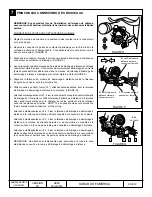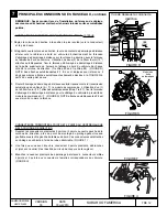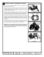
background image

5 OF 12

PART NUMBER

H001SFJ600

ISSUE

00

DATE

18 Jul 2013

SUBARU OF AMERICA

6

WINDSHIELD MOUNT ANTENNA INSTALLATION, continued

ANTENNA POD MOUNTING / HARNESS ROUTING

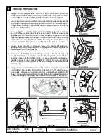
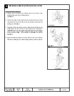
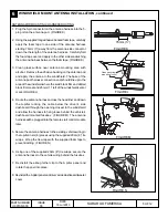
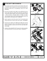
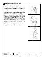
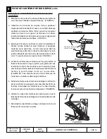
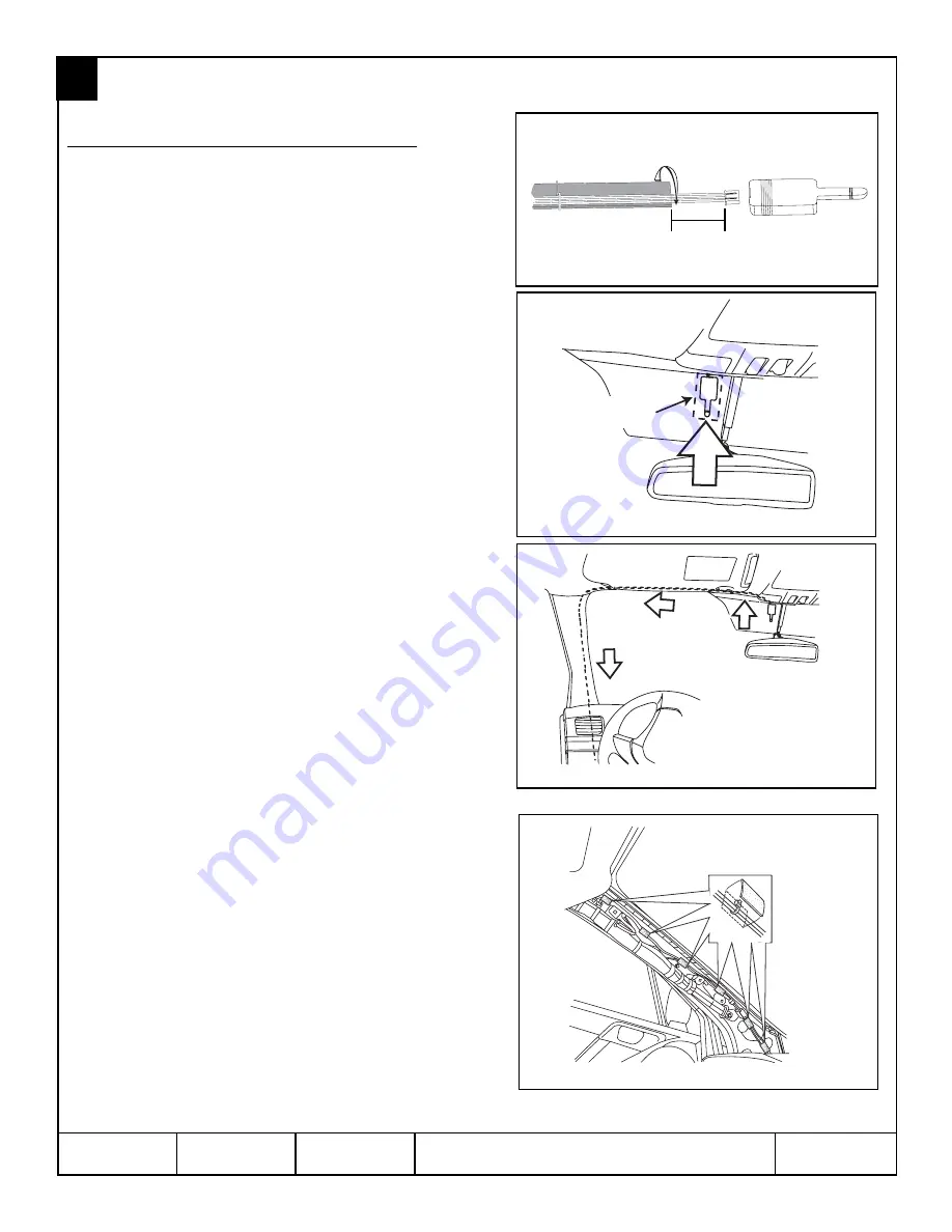
1. Plug the 5-pin connector on the antenna harness into the 5-

pin port on the antenna pod.  (FIGURE K)

2. Using the supplied long adhesive backed foam tape, carefully

apply the foam tape to one side of the antenna harness

starting 76mm (3”) away from the antenna side connector

down the the length of the antenna harness.  Carefully fold

the foam tape over and apply to the other side sandwiching

the antenna harness between the foam tape. (FIGURE K)

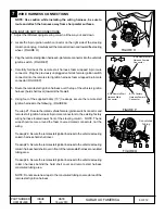
3. Clean glass surface near antenna mounting area with

alcohol.  Remove the adhesive backing on the antenna pod

and apply the antenna to the windshield. The base of the

antenna pod (harness connection end) should line up to the

area of the windshield where the solid black film and dotted

black film meet and 25mm (1”) left of the windshield center

mark. (FIGURE L)

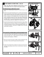
4. Route the antenna harness across the headliner and down

the A-pillar tucking the cable below the driver’s side

dashboard through the opening closest to the windshield

and allow the harness to hang loose behind the vehicle’s

dashboard mounted fusebox.  (FIGURE M)  The antenna

harness will be plugged into the remote start control module

later.

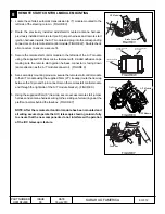
5.  Secure the antenna harness to the existing vehicle wiring in

the A-pillar in six (6) places using the supplied 20cm (8”) tie

wraps.  Wrap the tie wraps with the supplied foam tape to

prevent rattling.  (FIGURE N)

6. Using one of the supplied 20cm (8”) tie wraps, secure the

antenna harness to the vehicle wiring behind the fusebox.

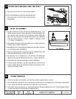
7. Re-install the airbag tether clip to the A pillar panel and

rotate the panel into place.

8.  Re-install the A pillar panel and driver’s side dashboard tweeter

cover.

FIGURE L

Clean mounting 
area with alcohol

FIGURE K

FIGURE M

FIGURE N

76mm (3”)

Summary of Contents for H001SFJ600

Page 1: ...ter The system will check certain pre conditions before starting and if all safety parameters are correct the engine will start within 5 seconds If the vehicle s starter cranks but does not start or s...

Page 2: ...access the Phillips screws on the face of the steering column 4 Using a panel removal tool carefully remove the driver s left side lower dashboard panel by pulling straight out Unplug all connectors a...

Page 3: ...ch to RES control module See section 7 2 Jumper harness connection to vehicle pre arranged connectors Located near the left side knee bolster airbag mount Routes from vehicle side pre arranged connect...

Page 4: ...body clips along with the lower clips where the A pillar panel meets the dashboard FIGURE I 3 Rotate theApillar panel away from the dashboard and release the the airbag tether clip from the top of the...

Page 5: ...of the windshield where the solid black film and dotted black film meet and 25mm 1 left of the windshield center mark FIGURE L 4 Route the antenna harness across the headliner and down the A pillar t...

Page 6: ...l 6 Using four of the supplied 39cm 15 tie wraps secure the remote start ignition harness to the following FIGURE Q Tie wrap 1 Secure the mated vehicle female ignition switch connector and remote star...

Page 7: ...E Q from an alternate view 3 Route the remote start ignition harness down towards the vehicle automatic transmission A T control module Using one 1 of the supplied 39cm 15 tie wraps Tie Wrap 7 secure...

Page 8: ...A T module connector FIGURE X 4 As a secondary mounting provision secure the remote start control module to theA T module using the supplied 53cm 21 tie wrap route the tie wrap between the 12 pin and...

Page 9: ...0 2 Kgf m 8 ft lbs 1 5 ft lbs The bottom of the hood safety switch bracket will fit securely against the top of the plastic fender wire harness grommet FIGURE AA 3 Plug the supplied remote start harn...

Page 10: ...irbag knee bolster and torque the bolts to 10 8 Nm 2 Nm 1 10Kgf m 0 2 Kgf m 8 ft lbs 1 5 ft lbs FIGURE EE 2 Re install the steering column shroud and secure in place with two 2 Phillips screws refer t...

Page 11: ...ic connector SDI screen will display Reg Remote Cont Eng Starter Yes ENT No C Confirm Ignition Sw On Press Ent The SDI screen will display Select Reg Sys Press ENT to select Immobi Sys SDI screen will...

Page 12: ...ned 4 BRAKE PEDAL SAFETY While sitting in the vehicle with all doors and hatch closed restart the vehicle using the remote engine starter press the brake pedal The vehicle should shut off 5 KEY IN SEN...

Page 13: ...hes 20cm Quantit 9 39cm Quantit 7 53cm Quantit 1 Starting Your Vehicle The remote control start function is activated by pressing the START key icon button twice within 3 seconds on your remote contro...

Page 14: ...ips sur la face de la colonne de direction 4 Avec un outil enl ve panneau enlevez d licatement le panneau inf rieur gauche du tableau de bord en tirant dessus directement D branchez tous les connecteu...

Page 15: ...lumage au module de commande RES Voir la section 7 2 Connexion du faisceau de Jumper v hicules connecteurs pr arrang Situ pr s du c t des genoux airbag montage gauche Routes du c t du v hicule pr disp...

Page 16: ...le panneau de pilierAr pond la planche de bord FIGURE I 3 Faire pivoter le panneau de pilier A l cart de la planche de bord et rel cher la pince de l attache d airbag partir du haut de la colonneA du...

Page 17: ...ion des pellicules noire et pois du pare brise et de 25 mm 1 gauche de la marque centrale FIGURE L 4 Acheminez le faisceau de l antenne le long du pavillon et faites le descendre le long du pied A pui...

Page 18: ...r le faisceau d allumage de d marrage distance la suivante FIGURE Q Attaches autobloquantes sur 1 Fixer le connecteur accoupl du v hicule femelle d allumage de l interrupteur et d but faisceau d allum...

Page 19: ...point de vue 3 Route l allumage de d marrage distance exploiter revenant vers la transmission automatique du v hicule A T le module de commande L utilisation d un 1 de la 39cm fourni 15 attaches auto...

Page 20: ...e de d marrage distance au module de bo te automatique avec l attache de 21 po fournie faites la passer entre les connecteurs 12 points et 5 points du module de d marrage distance du c t droit du supp...

Page 21: ...le Serrez le boulon 10 8 2 Nm 1 10 0 2 kgf m 8 1 5 lb pi Le bas du support de contacteurs de s curit doit tre appuy fermement contre le haut du passe fil en plastique de l aile FIGURE AA 3 Branchez le...

Page 22: ...C 3 Remontez le panneau inf rieur droit du tableau de bord et fixez le avec une 1 vis Phillips FIGURE E 4 Rebranchez tous les connecteurs d branch s au d montage et remontez le panneau inf rieur gauc...

Page 23: ...de contact dans le cylindre d allumage et tourner sur la position RUN MARCHE Continuer de presser simultan ment pendant pr s de 5 secondes les touches SDI Menu et C pour entrer dans le mode autonome P...

Page 24: ...uvercle du coffre 4 S CURIT DE FREINAGE Assis au volant du v hicule avec toutes les portes ferm es y compris le hayon ou couvercle du coffre red marrez avec le syst me de d marrage distance puis appuy...

Reviews: