background image

4 OF 7

PART NUMBER

H001SFL300

ISSUE

00

DATE 

22 Jun 2018

SUBARU OF AMERICA

6

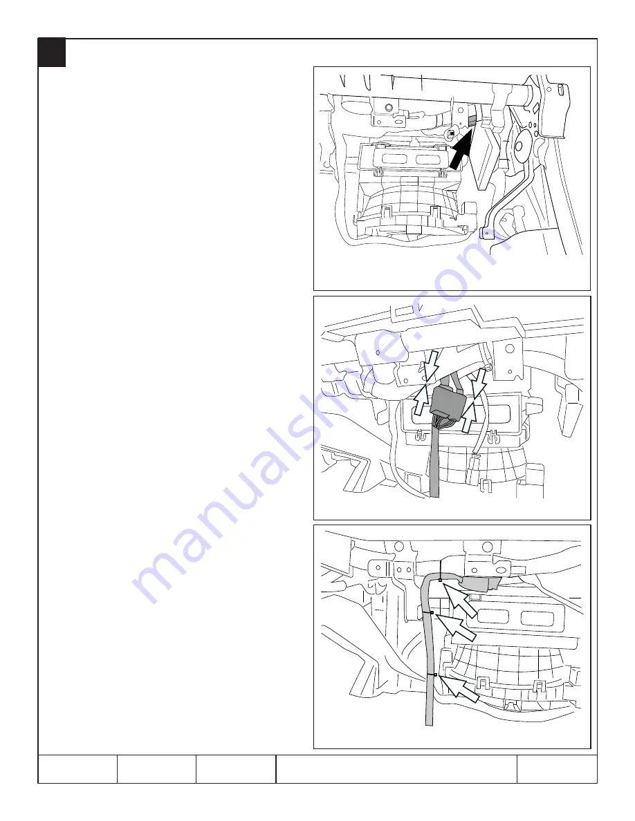
1.  Locate and release the vehicle’s 8-pin and 2-pin pre-fi t 

connectors secured to the vehicle’s wire harness with 

breakaway tape near the upper passenger’s side glove 

box area.  (FIGURE J)

2.  When the vehicle’s 8-pin and 2-pin pre-fi t connectors 

are free from the breakaway tape, unplug and discard 

the 2-pin mating connector/wire jumper.  (This is used 

for the power window interrupt circuit).

3.  Plug the remote engine start pre-arranged jumper 

harness 8-pin and 2-pin connectors into the 

corresponding pre-fi t connectors.  (FIGURE K)

4.  Secure the pre-arranged jumper harness to the vehicle’s 

wire harness using three (3) of the supplied 20cm tie 

wraps.  Trim off the excess tie wraps.  (FIGURE L)

5.  Plug the pre-arranged jumper harness 12-pin connector 

into the 12-pin white port on the remote engine start 

ECU, previously mounted to the back side of the glove 

box inner cover (Step 5).

PRE-ARRANGED JUMPER HARNESS CONNECTIONS

FIGURE J

FIGURE K

FIGURE L

Summary of Contents for H001SFL300

Page 1: ...l be disabled The engine will continue to run for fifteen 15 minutes unless one of the safety parameters below is triggered The system also has a timer that will allow the system to operate for a maximum of twenty 20 minutes under multiple remote start activations Using the factory ignition key Turn start models or Access key Push button start models to turn on the ignition resets the twenty 20 mi...

Page 2: ...tool carefully remove the right side dashboard panel by starting at the bottom access notch and working upward to disengage four 4 pressure clips FIGURE C 4 Using a panel removal tool carefully lift upward to disengage 4 pressure clips and one 1 finger clip and then pull rearward to remove the passenger s side ornament panel FIGURE D 5 Using a Phillips screwdriver remove seven 7 Phillips screws se...

Page 3: ...e sided tape is positioned away from any obstructions on the glove box inner cover 2 Remove the one 1 large release liner from the double sided tape and attach the remote engine start ECU Ensure the corner of the ECU closest to the small gray connector is flush with the upper left corner of the tape as shown Press firmly in place for at least 30 seconds FIGURE H NOTE Ensure the ECU connectors will...

Page 4: ...umper This is used for the power window interrupt circuit 3 Plug the remote engine start pre arranged jumper harness 8 pin and 2 pin connectors into the corresponding pre fit connectors FIGURE K 4 Secure the pre arranged jumper harness to the vehicle s wire harness using three 3 of the supplied 20cm tie wraps Trim off the excess tie wraps FIGURE L 5 Plug the pre arranged jumper harness 12 pin conn...

Page 5: ...r 4 pressure clips and one 1 finger clip 3 Re install the right side dashboard panel by engaging the four 4 pressure clips 4 Re install the glove box and strut 5 At the end of the installation insert the Quick Reference Cards into the Owner s Information Kit 8 UNDER HOOD WARNING LABEL MOUNTING 1 Using alcohol clean the top of the air intake plenum near the radiator core support 2 Remove the releas...

Page 6: ...ows on the DST i select Immobilizer Using the arrows on the DST i select YES DST i screen will display Check if Ignition SW is turned ON Using the arrows on the DST i select YES Using the arrows on the DST i select Remote Engine Start CM Registration DST i screen will display Successful Remote Engine Start CM Registration Press OK Using the arrows on the DST i select YES PRESS A PRESS A Using the ...

Page 7: ...icle the engine hood all doors and trunk or hatch are closed and the driver s door is unlocked Press the START button on the remote start transmitter two 2 times within three 3 seconds The vehicle s parking lights should flash and the vehicle s horn should honk six 6 times The vehicle should not start with the driver s door unlocked 4 ACTIVATION WITH DOOR OPEN Ensure the Access key is removed from...

Reviews: