5 OF 12
PART NUMBER
H001SSG400
ISSUE
00
DATE
27 May 2013
SUBARU OF AMERICA
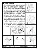
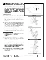
20mm
10mm
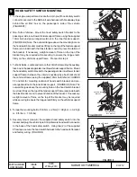
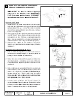
FIGURE P
6
WINDSHIELD MOUNT ANTENNA INSTAL-
LATION - EYESIGHT EQUIPPED VEHICLES
IMPORTANT! THIS SECTION ONLY APPLIES
TO VEHICLES EQUIPPED WITH THE
EYESIGHT SYSTEM. FOR VEHICLES
WITHOUT THE EYESIGHT SYSTEM,
DISREGARD THIS SECTION AND RETURN
TO SECTION 5
ANTENNA MOUNTING
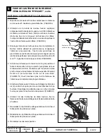
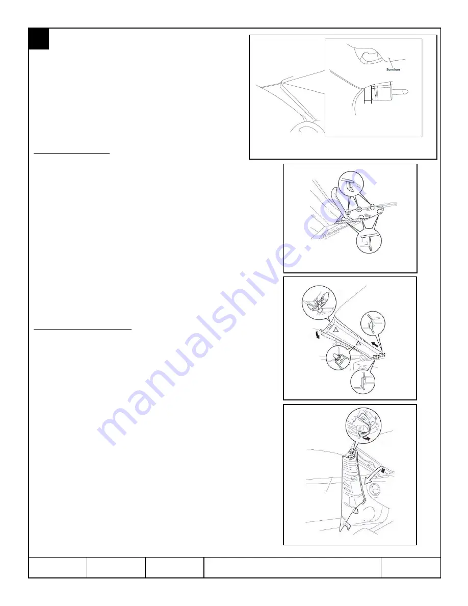
1. Mount the antenna pod to the top left hand side of the
windshield, near the headliner and driver’s side A-pillar trim
panel with the antenna pod “finger” facing the passenger’s
side. Use alcohol to clean the area thoroughly.
(FIGURE P)
2. The top left corner of the antenna pod should be 20mm
(3/4”) from the right corner of the A-pillar trim panel in a
straight line and 10mm (3/8”) down from the headliner to the
upper right corner of the antenna pod. Note: The antenna
pod should be level left to right. (FIGURE P)
3. Remove the adhesive backing and apply the antenna pod to
the windshield as described in step 2 above. (FIGURE P)
A-PILLAR PANEL REMOVAL
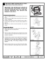
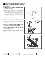
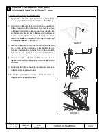
1. Using a panel removal tool, carefully remove the driver’s side
dashboard tweeter cover by lifting upward.
(FIGURE Q)
2. Remove the driver’s side A pillar panel by releasing the two
(2) body clips along with the lower clips where the A pillar
panel meets the dashboard. (FIGURE R)
3. Rotate the A pillar panel away from the dashboard and release
the the airbag tether clip from the top of the A pillar panel.
(FIGURE S)
CAUTION! Use care when performing this
step to avoid damage to the curtain airbag. If the
airbag is damaged, it must be replaced.
4. Inspect the white protective (non-woven fabric) of the curtain
airbag. If the fabric is damaged, the curtain airbag assembly
must be replaced.
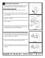
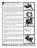
FIGURE N
FIGURE Q
FIGURE R
FIGURE S

