background image

2 OF 11

PART NUMBER

H011SAJ400

ISSUE

00

DATE

21 Apr 2013

SUBARU OF AMERICA

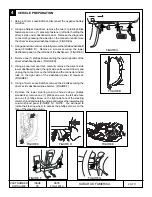
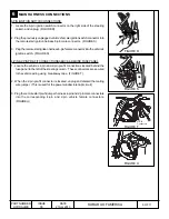
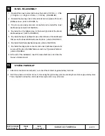
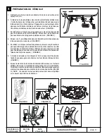
1.  Using a 10 mm socket/ratchet, disconnect the negative battery

terminal.

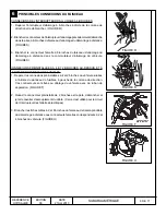
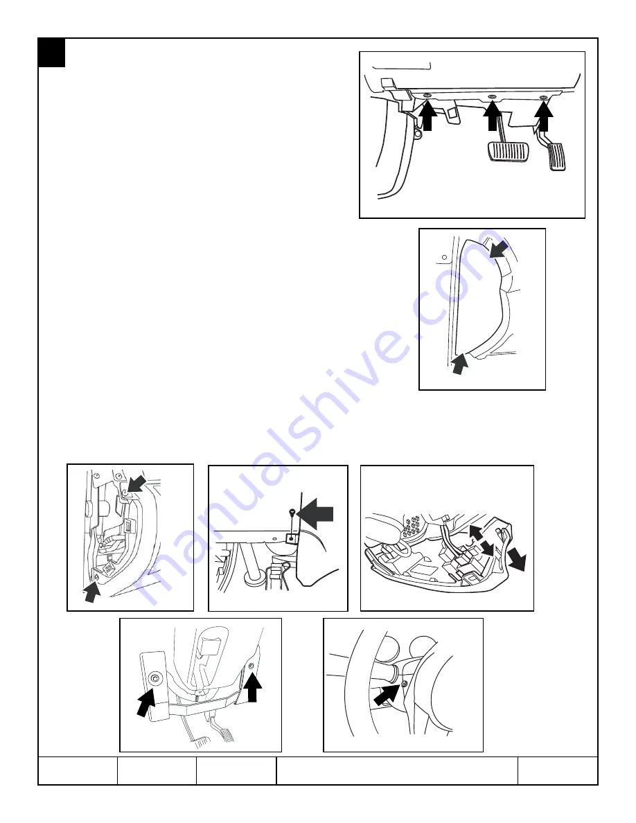
2. Using a phillips screwdriver, remove the two (2) plastic phillips

fasteners and one (1) pressure fastener (left side) holding the
driver’s side under dashboard panel.  Release the diagnostic
connector by pressing the side clip on the connector and remove
the driver’s side under dashboard panel.  (FIGURE A)

3. Using a panel removal tool, carefully remove the left side dashboard

panel (FIGURE B).  Remove 2 screws securing the lower
dashboard panel on the left side of the dashboard.  (FIGURE C)

4. Remove one (1) phillips screw securing the lower right side of the

driver’s dashboard panel.  (FIGURE D)

5.  Using a panel removal tool, carefully remove the driver’s side

lower dashboard panel (the right side pulls out and down) and
unplug the connectors on the left side and the connector and air
tube on the right side of the dashboard panel (if required).
(FIGURE E)

6. Using a 10 mm socket/ratchet, remove the 2 bolts securing the

driver’s side dashboard knee bolster.  (FIGURE F)

7.  Remove the lower steering column shroud using a phillips

screwdriver, remove one (1) phillips screw on the left side face
and one (1) phillips screw on the right side face of the steering
column shroud and carefully unsnap and remove the lower steering
column shroud panel (FIGURE G).  NOTE:  You will need to
rotate the steering wheel to access the phillips screws on the
face of the steering column.

4

VEHICLE PREPARATION

FIGURE C

FIGURE D

FIGURE B

FIGURE A

FIGURE E

FIGURE G

FIGURE F

Summary of Contents for H011SAJ400

Page 1: ...e within 3 seconds on your remote control transmitter The system will check certain pre conditions before starting and if all safety parameters are correct the engine will start within 5 seconds If th...

Page 2: ...of the driver s dashboard panel FIGURE D 5 Using a panel removal tool carefully remove the driver s side lower dashboard panel the right side pulls out and down and unplug the connectors on the left s...

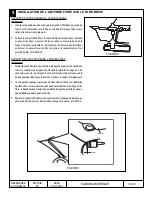
Page 3: ...e the solid black film and dotted black film meet FIGURE H ANTENNA POD MOUNTING VEHICLES WITH EYESIGHT 1 Mount the antenna pod to the top left hand side of the windshield against the headliner near th...

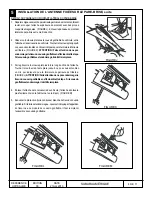
Page 4: ...orming this step to avoid damage to the curtain airbag If the airbag is damaged it must be replaced 3 Slide the flatblade screwdriver further along the side of the clip Twist the flat blade screwdrive...

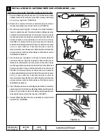
Page 5: ...enna harness at the antenna pod connection point and verify the harness is routed in a manner to avoid sharp edges or interference with panel re installation 4 Vehicles with Eyesight Route the antenna...

Page 6: ...connector into the vehicle s ignition switch FIGURE S 4 PIN 2 PIN PRE FITCONNECTIONSABOVE BEHIND FUSE PANEL 1 Locate the vehicle s 4 pin and 2 pin pre fit connections located behind the fuse panel to...

Page 7: ...ie wrap route the tie wrap between the 12 pin and 5 pin connectors on the remote start control module and through the right side of theA T module bracket FIGUREX 5 Using the supplied 8 tie wrap secure...

Page 8: ...top mounted 10mm mounting bolt Torque both mounting bolts to 10 8 Nm 2 Nm 1 10 Kgf m 0 2 Kgf m 8 ft lbs 1 5 ft lbs 5 Securely mount snap in the supplied hood safety switch into the bracket and plug t...

Page 9: ...roud and secure in place with two 2 phillips screws refer to FIGURE G 3 Plug in any previously removed connectors and re install the lower dashboard panel refer to FIGURE E 4 Re install one 1 phillips...

Page 10: ...ss C and proceed to Remote Start Registration if no additional keys are available The SDI screen will display Execute Key Reg SDI screen will display Execute Key Reg ENTER ENTER Proceed to 3 rd Key Re...

Page 11: ...4 BRAKE PEDAL SAFETY While sitting in the vehicle with all doors and hatch trunk closed restart the vehicle using the remote engine starter press the brake pedal The vehicle should shut off 5 KEY IN S...

Page 12: ...cule avant d effectuer des travaux d entretien sur celui ci Starting Your Vehicle The remote control start function is activated by pressing the START key icon button twice within 3 seconds on your re...

Page 13: ...ableau de bord du conducteur FIGURE D 5 En utilisant un outil pour enlever les panneaux enlever avec pr caution le panneau inf rieur gauche du tableau de bord du c t conducteur le c t droit s enl ve e...

Page 14: ...le film noir plein et le rassemblement noir pointill de film FIGURE H SUPPORTDE COSSE D ANTENNE V HICULESAVEC EYESIGHT 1 Montezlacossed antenneauc t demaingauchesup rieurdupare brise contre le vedette...

Page 15: ...ne pas endommagerletissuducoussingonflableeneffectuantcette tape Silecoussingonflableestendommag ildoit treremplac 3 Faire glisser le tournevis plat plus loin le long du c t de l attache Tourner le t...

Page 16: ...cossed antenneetv rifierleharnaisestconduiten quelque sorte pour viter les bords pointus ou l interf rence avec la r installation de panneau 4 Des v hicules avec Eyesight Conduisez le harnais d antenn...

Page 17: ...E S CONNEXIONS PR INSTALL ES 4 ET 2 BROCHES AU DESSUS ET L ARRI RE DU PANNEAU DE FUSIBLES 1 Rep rer les connexions pr install es 4 et 2 broches du v hicule situ es l arri re du panneau de fusibles gau...

Page 18: ...module de contr le et par le c t droit du support du module A T FIGURE X 5 l aide des attaches autobloquantes de 20 cm 8 po fournies fixer le faisceau de liaison du d marrage distance et le faisceau...

Page 19: ...de 10 mm arri re par le dessus Serrer les deux boulons de montage au couple de 10 8 Nm 2 Nm 1 10 Kgf m 0 2 Kgf m 8 pi lb 1 5 pi lb 5 Monter solidement en appuyant l interrupteur de s curit capot fourn...

Page 20: ...de direction et le fixer en position l aide de deux 2 vis phillips voir FIGURE G 3 Brancher tout connecteur pr c demment retir et r installer le panneau inf rieur du tableau de bord voir FIGURE E 4 R...

Page 21: ...nt L cran SDI invite donner le code d op ration de 4 caract res num riques Entrer le code en utilisant les fl ches sur le SDI L cran SDI invite donner le l identification de s curit de 5 caract res nu...

Page 22: ...lon ouvert 4 S CURIT P DALE DE FREIN Apr s s tre assis dans le v hicule avec toutes les portes et le coffre ou le haillon ferm s red marrer le v hicule en utilisant le d marrage distance du moteur pui...

Reviews: