5 OF 11
PART NUMBER
H011SAJ400
ISSUE
00
DATE
21 Apr 2013
SUBARU OF AMERICA
5
WINDSHIELD MOUNT ANTENNA INSTALLATION, continued
ANTENNA POD MOUNTING / HARNESS ROUTING
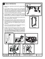
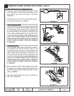
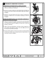
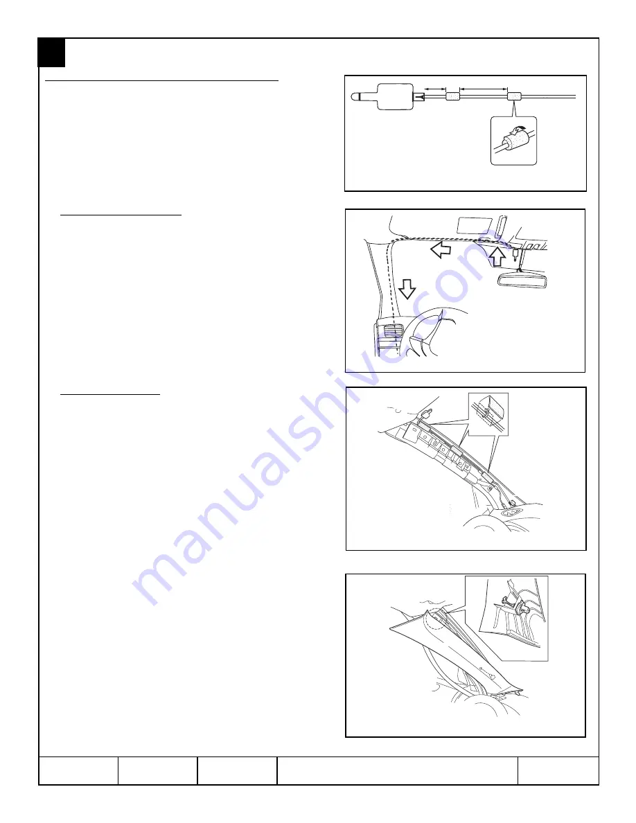
1. Wrap one (1) piece of the supplied foam tape around the
antenna harness 76 mm from the connector and a second
piece 152 mm away from the first piece of foam tape.
(FIGURE N)
2. Plug the 5-pin connector on the antenna harness into the 5-
pin port on the antenna pod. (FIGURE N)
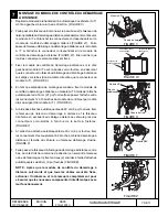
3. Vehicles without Eyesight - Route the antenna harness
across the headliner and down the A-pillar tucking the cable
below the driver’s side dashboard through the opening closest
to the windshield and allow the harness to hang loose behind
the vehicle’s dashboard mounted fusebox. (FIGURE O) The
antenna harness will be plugged into the remote start control
module later.
Note: Use care to ensure that there is no
stress on the antenna harness at the antenna pod
connection point and verify the harness is routed in a
manner to avoid sharp edges or interference with panel
re-installation.
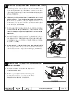
4. Vehicles with Eyesight - Route the antenna harness directly
into and down the A-pillar tucking the cable below the driver’s
side dashboard through the opening closest to the
windshield and allow the harness to hang loose behind the
vehicle’s dashboard mounted fusebox. (FIGURE P) The
antenna harness will be plugged into the remote start control
module later.
Note: Use care to ensure that there is no
stress on the antenna harness at the antenna pod
connection point and verify the harness is routed in a
manner to avoid sharp edges or interference with panel
re-installation.
5. Secure the antenna harness to the existing vehicle wiring in
the A-pillar in three (3) places using the supplied 8” tie wraps.
Wrap the tie wraps with the supplied foam tape to prevent
rattling. (FIGURE P)
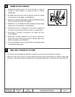
6. Install the supplied A-pillar trim clip and re-install the A-
pillar panel. (FIGURE Q)
6"
3"
FIGURE N
FIGURE O
FIGURE Q
FIGURE P

