3
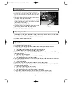
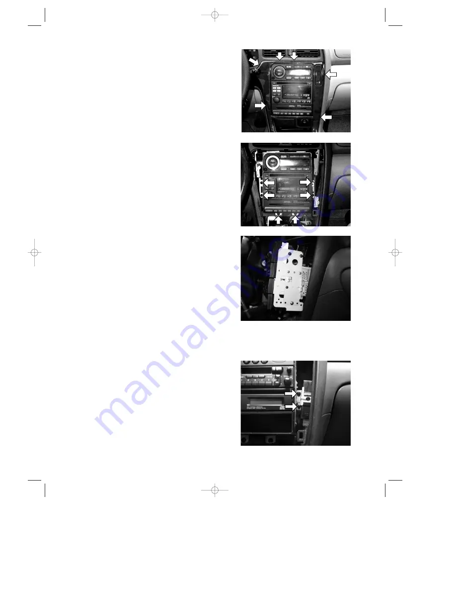
Figure 4
Figure 5
Figure 6
4. Lift the center console cover by carefully pulling
outward in areas indicated by arrows in Figure 4.
5. Remove the six screws indicated by the arrows in
Figure 5. Do not disconnect any connectors. Pull the
unit out just far enough to access the passenger side
of the unit. See Figure 6.
NOTE: While the HVAC unit is pulled foward,
the ASPIRATOR SENSOR hose (located
on the driver’s side of the HVAC unit)
may disconnect. The hose must be recon-
nected during re-installation.
6. Install the security radio mounting bracket per
Figure 6, by first removing all radio, CD, etc. mount-
ing screws visible on passenger side of car radio
bracket. Locate and install security radio mounting
bracket utilizing these screws.
7. Locate the security module 18-pin (white housing)
wire harness connector which is located behind or to
the right side of the audio unit.
8. Re-install the radio assembly. Insure all connectors
and ground wires are fully seated and secure.
Insure that the HVAC unit is functioning properly.
9. Insert the security module 18-pin connector into the
security module.
10. Mount the security module onto the support bracket
with two screws (M5
×
8mm). See Figure 7.
NOTE: The security module must be firmly and
securely fastened to the support bracket.
If the security module is not properly
installed, the system’s shock sensor will
not function as intended.
Figure 7
39412/SUBARU (P.01-09)5ÇÃÉRÉsÅ[ 8/28/00 11:42 AM Page 3

