


9
InstAllAtIon InstructIons
SDN2 • SDN3
WARNING! Installation of this appliance must be made in accordance with
the written instructions provided in this manual. No agent, representative
or employee of Suburban or other person has the authority to change,
modify or waive any provision of the instructions contained in this
manual.
1.
In the U.S.A., the installation must conform with state or other codes or in the
absence of such codes, refer to the latest edition of:
a.
Standard for Recreational Vehicles NFPA 1192.
b.
National Fuel Gas Code ANSI Z223.1/NFPA 54
In Canada, the installation must be in accordance with:
a.
Standard CAN/CSA 240.4.2-08, Installation Requirements for Propane
Appliances and Equipment in Recreational Vehicles.
b.
Any applicable local codes and regulations
2.
Minimum clearances from combustible walls above and below counter:
Models
Below Counter Center of Burner Head(s) to adjacent vertical
combustible material above the cooking surface
burners.
Sides, Rear and
Bottom
Right Sidewall
Left Sidewall
Backwall
SDN2
0”
5 7/8”
5 7/8”
8”
SDN3
0”
5 5/8”
6”
8”
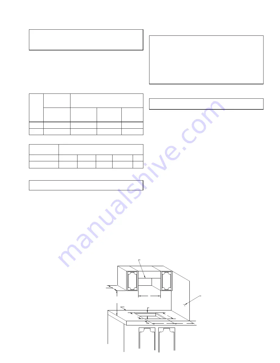
3.
Cut-out dimensions illustrated in Figure 2 are as follows:
Model
Dimensions
A B C* D* E
SDN2
16 3/8”
11 5/8”
2 3/16”
3/4” min.
18”
SDN3
18 15/16”
16 1/8”
2 1/16”
2 3/8” min.
21”
*Minimum acceptable spacing between adjacent models is 3 inches.
WARNING: Installation of cook top cannot be such that the user is
required to reach over any of the burners to reach the knobs.
4.
Before placing drop-in cook top into cabinet, determine which one of the three
knockout openings in the burner box (left side, right side or rear) will be used for
routing of the gas supply tubing to the pressure regulator. After making selection,
knockout the 1 inch plug. Place drop-in cook top into the prepared opening and
secure to cabinet with four (4) wood screws. (Not provided)
NOTE: For models with a manifold extension, place the drop-in cook top
into the prepared opening and secure to the cabinet with four (4) wood
screws. (Not provided)
5.
Route gas line through opening in burner box and connect the gas line to the
3/8” flare fitting inside the burner box. Place nylon bushing over gas line and insert
bushing into opening in burner box.
NOTE: For models with a manifold extension, connect the gas line to the
3/8” flare fitting just outside the burner box. Be sure to hold the fitting on
the extension with a wrench when tightening the flare nut. Failure to hold
fitting secure could result in a gas leak due to fitting being damaged.
CAUTION: Gas supply tubing within the confines of the appliance burner
box shall be rigid or semirigid metallic tubing.
6.
Be sure all openings in the cabinets around the gas line are sealed at time of
installation.
CAUTION: It is imperative that the cabinet in which the cook top is placed
be separated from other appliances so that the combustion air supply to
the top burners can not be affected in any way by any forced-air heating
appliance or its return air system or by any other source of positive or
negative air pressure. A negative air pressure created by another forced
air appliance may draw the flame down around the top burners and into
the cook top resulting in damage to the burners and cook top, as well
as possible personal injury and/or damage to vehicle. A positive draft
could cause the burner flame to lift-off the burner and go out resulting
in an uncontrolled escape of gas. Whenever the gas fumes reach an
open flame or another ignition source, an explosion and/or fire will occur
resulting in property damage, personal injury and/or loss of life.
7.
Be sure burner knobs are in “off” position. Turn on gas supply. Check all
connections for leaks.
WARNING: Never check for leaks with an open flame. Apply a
soap and water solution to all joints to see if bubbles are formed.
notE:
The appliance must be disconnected from the gas supply piping system
during any pressure testing of that system at test pressure in excess of 1/2 PSIG.
8.
Remove the top and the grate(s) from their packing - Install the grate(s) on the
top.
9.
Position the top over the burners and secure in place with two (2) thumb screws
and two (2) nylon washers provided.
10.
Your Suburban Drop-in Cooktop is now ready for operation. Before operating,
read the safety information and operating instructions contained in the installation
manual.
11.
If installation of this product is in a portable counter top, the following additional
guidelines must be followed:
a.
Portable counter top is provided by installer and must be able to
support a minimum weight of 20 lbs.
b.
OEM must provide a label placed on the counter top that clearly states
the maximum weight that can be added to the portable counter top after
installation. (This should take into account the weight of the cooking unit
- 20 lbs).
FOR EXAMPLE:
Mounting bracket used is rated for 100 lbs. OEM
should weigh fabricated counter top. Subtract weight of counter top (i.e.
20 lbs) and weight of cooking unit (20 lbs.) from 100 lbs. The weight label
should say no more than 60 lbs. can be put on the counter top.
c.
The surface material for the counter top must be rated for a minimum
of 200°F continuous operation temperature with the maximum weight
applied.
d.
Minimum clearances from combustible walls above and below the
counter top must be adhered to during operation.
e.
The OEM must provide a warning label placed on the counter top
that requires the unit to be cooled a minimum of 30 minutes after use
before storing.
f.
During storage, a clearance of 1” must be maintained from the top
surface of the unit.
g. notE:
The gas must be turned “OFF” and disconnected when stored.
A
4"
3 1/8"
18"
E
MIN.
C
MINIMUM DISTANCE TO COMBUSTIBLE SURFACES
DIRECTLY ABOVE COOK-TOP 24"
*D
WALL
*C-SEE UL LABEL
*
13" MAXIMUM OVERHEAD
CABINET DEPTH
B
REAR
FRONT


