background image

General Information

2

Component Access & Removal

4

Troubleshooting Guide

44

Technical Data

53

Wiring Diagrams

54

subzero.com    800.222.7820

Convection Steam Oven

Service Manual

Summary of Contents for WOLF CSO

Page 1: ...General Information 2 Component Access Removal 4 Troubleshooting Guide 44 Technical Data 53 Wiring Diagrams 54 subzero com 800 222 7820 Convection Steam Oven Service Manual...

Page 2: ...images contained herein may be copied or used in whole or in part without the express written consent of Wolf Appliance Inc Wolf Appliance Inc all rights reserved WOLF PRODUCT RATING PLATE INFORMATION...

Page 3: ...subzero com ClaimsAndOrderProcessing Pages WarrantyInfo Warranties start on the day of product installation Search for warranty and service information by serial number customer last name and address...

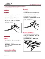
Page 4: ...EMOVAL To remove the door front first remove the door Remove the Door 1 Open the door 2 Rotate the hinge retainer clip on each hinge forward until the hinge retainer clip stops 3 Close the door until...

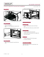
Page 5: ...e the door then separate the door front and the inner door Remove the Door 1 Open the door 2 Rotate the hinge retainer clip on each hinge forward until the hinge retainer clip stops 3 Close the door u...

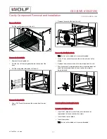
Page 6: ...hinge retainer clips on each hinge backward until the hinge retainer clips stop 5 Test the door INTERMEDIATE DOOR GLASS REMOVAL To remove the intermediate door glass first remove the door then separa...

Page 7: ...ft the bottom of the door front above the lower bracket of the inner door 4 Pull the door front down over the inner door bracket 5 Use a T 10 Torx bit to install the left and right inner door mounting...

Page 8: ...ack guide toward the center of the oven 3 Pull the rack guide forward out of the unit RACK GUIDE INSTALLATION Install the Rack Guide 1 Insert the rack guide rails into the rear baffle 2 Place the inde...

Page 9: ...onto the food probe cover 2 Place the food probe cover over the food probe switch threads 3 Use an 11 mm socket to install the food probe nut Install the Rack Guide 1 Insert the rack guide rails into...

Page 10: ...n light bulb 1 Insert the halogen light bulb into the socket 2 Install the oven light seal into the oven light frame assembly if it was removed 3 Place the oven light safety glass onto the oven light...

Page 11: ...the rear baffle against the back wall of the oven cavity 2 Use a T 20 Torx bit to install the screws into the rear baffle Install the Rack Guide 1 Insert the rack guide rails into the rear baffle 2 Pl...

Page 12: ...1 Use a 10 mm socket to remove the nut from the hot air fan blade 2 Remove the washer and the hot air fan blade from the unit 3 The washer and C clip behind the hot air fan blade does not need to be...

Page 13: ...is procedure To remove the element first remove the racks rack guides and rear baffle Remove the Rack Pull the rack forward out of the unit Remove the Rack Guide 1 Remove the rack guide nut 2 Pull the...

Page 14: ...Place the rear baffle against the back wall of the oven cavity 2 Use a T 20 Torx bit to install the screws into the rear baffle Install the Rack Guide 1 Insert the rack guide rails into the rear baff...

Page 15: ...it 2 Remove the top plate from the unit TOP PLATE INSTALLATION Install the Top Plate 1 Place the top plate on the unit 2 Use a T 20 Torx bit to install the screws into the top plate DOOR SWITCH REMOVA...

Page 16: ...lve assembly first remove the water tank and the top plate Remove the Water Tank 1 Touch Water on the control panel 2 Remove the water tank from the unit Remove the Top Plate 1 Use a T 20 Torx bit to...

Page 17: ...water tank closed TANK HOUSING COVER REMOVAL To remove the tank housing cover first remove the top plate Remove the Top Plate 1 Use a T 20 Torx bit to remove the screws from the top and back of the un...

Page 18: ...ank housing cover 2 Use a T 10 Torx bit to remove the screws from the tank housing cover 3 Remove the tank housing cover from the unit Remove the Valve Assembly 1 Remove the electrical connectors from...

Page 19: ...s into the tank housing cover 3 Install the wire harness clips onto the tank housing cover Install the Top Plate 1 Place the top plate on the unit 2 Use a T 20 Torx bit to install the screws into the...

Page 20: ...orx bit to install the screws into the top plate DISPLAY REMOVAL To remove the display first remove the top plate and the control board Remove the Top Plate 1 Use a T 20 Torx bit to remove the screws...

Page 21: ...the ribbon cable connectors and lock the ribbon cable connector 4 Connect the electrical connectors to the control board Install the Top Plate 1 Place the top plate on the unit 2 Use a T 20 Torx bit t...

Page 22: ...drive motor tab from the tank housing cover 5 Use a T 10 Torx bit to remove the screws from the valve assembly 6 Remove the valve assembly from the unit Remove the Tank Housing Base 1 Use a T 20 Torx...

Page 23: ...panel from the unit 4 Turn the control panel over 5 Use a T 20 Torx bit to remove the screws from the control board bracket 6 Remove the control board bracket from the control panel CONTROL PANEL INST...

Page 24: ...ly electrical connectors 6 Connect the water tank microswitch electrical connectors Install the Tank Housing Cover 1 Place the tank housing cover onto the tank housing base 2 Use a T 10 Torx bit to in...

Page 25: ...1 Use a T 20 Torx bit to remove the screws from the top and back of the unit 2 Remove the top plate from the unit Remove the Loudspeaker 1 Disconnect the loudspeaker electrical connector from the con...

Page 26: ...the top exhaust duct 2 Use a T 15 Torx bit to install the screw into the temperature sensor 300C 3 Connect the temperature sensor 300C electrical connector to the unit relay board Install the Top Pla...

Page 27: ...plate loudspeaker room air fan motor temperature sensor 300C and stepper motor Remove the Top Plate 1 Use a T 20 Torx bit to remove the screws from the top and back of the unit 2 Remove the top plate...

Page 28: ...nt of the unit 3 Remove the stepper motor from the unit Remove the Top Exhaust Duct 1 Use a T 20 Torx bit to extract the screws from the top exhaust duct 2 Push the top exhaust duct toward the rear of...

Page 29: ...t 2 Rotate the loudspeaker clockwise until the arrow on top of the loudspeaker is pointing to the front of the unit 3 Connect the loudspeaker electrical connector to the control board Install the Top...

Page 30: ...to pry the tabs up on the stepper motor retainer while pulling the stepper motor toward the front of the unit 3 Remove the stepper motor from the unit Remove the Top Exhaust Duct 1 Use a T 20 Torx bi...

Page 31: ...epper motor tabs lock into place 2 Connect the electrical connector to the stepper motor Install the Temperature Sensor 300C 1 Insert the temperature sensor 300C into the top exhaust duct 2 Use a T 15...

Page 32: ...it 2 Use a T 20 Torx bit to install the screw into the temperature sensor 3 Connect the temperature sensor electrical connector to the control board Install the Top Plate 1 Place the top plate on the...

Page 33: ...he screws from the top and back of the unit 2 Remove the top plate from the unit Remove the Thermostat 280C 1 Disconnect the electrical connectors from the thermostat 280C 2 Use a 9 32 socket to remov...

Page 34: ...2 Place the cable clamp and power cord in the unit 3 Install the cable protector onto the power cord 4 Connect the power cord electrical connectors to the unit relay board and the back of the unit In...

Page 35: ...fan motor first remove the top plate racks rack guides rear baffle and the hot air fan blade Remove the Top Plate 1 Use a T 20 Torx bit to remove the screws from the top and back of the unit 2 Remove...

Page 36: ...Convection Fan Motor 1 Place the convection fan motor onto the back of the unit 2 Use a T 20 Torx bit to install the screws into the convection fan motor 3 Connect the electrical wires to the convecti...

Page 37: ...rain pump assembly from the drain pump retainer 5 Disconnect the electrical connector from the drain pump assembly 6 Remove the drain pump assembly from the unit DRAIN PUMP ASSEMBLY INSTALLATION Insta...

Page 38: ...N Install the Drain Pump Retainer 1 Place the drain pump retainer onto the absorbers 2 Pull the absorber nipple through the holes in the drain pump retainer Install the Drain Pump Assembly 1 Connect t...

Page 39: ...the condenser water nozzle to the evaporator 5 Connect the hose from the evaporator to the drain pump suction 6 Connect the electrical connector to the level measure pin 7 Connect the electrical conne...

Page 40: ...o the level measure pin Install the Evaporator 1 Connect the electrical connector to the temperature sensor 2 Insert the evaporator into the retaining tabs on the unit 3 Use a flat blade screwdriver t...

Page 41: ...Remove the temperature sensor 100C and grommet from the unit TEMPERATURE SENSOR 100C INSTALLATION Install the Temperature Sensor 100C 1 Insert the grommet into the evaporator 2 Insert the temperature...

Page 42: ...the unit Remove the Food Probe Cover 1 Lift the food probe cover 2 Use an 11 mm socket to remove the food probe cover nut 3 Remove the food probe cover nut and food probe cover seal from the unit Remo...

Page 43: ...k guide nut Install the Rack 1 Insert the rack between the rails of the rack guide 2 Push the rack into the oven PTC HEATER REMOVAL WARNING Turn off the power to the product before starting this proce...

Page 44: ...ncompatible Reload software error 1 Turn the power to the unit off and then back on 2 Replace the relay board E9 F0 Temperature sensor short circuit Short circuit in the temperature sensor or control...

Page 45: ...or contact in food probe socket 1 Plug in the food probe 2 Measure the resistance on the X4 connector between X4 2 amd X4 3 2 Replace the food probe 3 Replace the food probe socket 4 If error occurs...

Page 46: ...ard for excessive moisture 3 Replace the control board E33 F12 Temperature relay board short circuit Excessive moisture on the relay board 1 Inspect the relay board for excessive moisture 2 Inspect fo...

Page 47: ...3 stuck Element or relay board damaged 1 Check the resistance of the element 2 Check the resistance of the element to ground 3 Replace the relay board E46 F8 Actuator relay K4 stuck Element or relay b...

Page 48: ...1 Problem with the power supply 2 Moisture on the relay board 3 Replace the relay board E59 U1 L1 voltage under voltage Voltage at L1 was between 155 VAC and 176 VAC 1 Problem with the power supply 2...

Page 49: ...eplace the relay board E72 F21 Open circuit in water tank drive motor 1 Check the water tank drive motor wiring 2 Replace the valve assembly 3 Replace the relay board E74 F22 Retractable door handle n...

Page 50: ...during normal operation 1 Slider is blocked with grease 2 Slider mechanism is too tight Replace the slider E88 Slider in stop position Path of slider is restricted during normal operation 1 Slider is...

Page 51: ...rol board for moisture 2 Replace the control board if the error continues E107 Operating system NVRAM FLASH structure data error Moisture on control board 1 Inspect the control board for moisture 2 Re...

Page 52: ...Reload the software 2 Replace the control board E124 F5 MODELCONFIGLIBRA RY error 1 Reload the software 2 Replace the control board E125 F5 PRESENTATIONLIBRA RY error 1 Reload the software 2 Replace t...

Page 53: ...10 230 VAC PTC Heater Measured at X17 1 2 310 Water Tank Drive Motor 140 Drain Pump 88 Stepper Motor Measured at X10 1 2 88 Temperature Sensor 1090 Loudspeaker 7 Temperature Sensor 300C 255 k Evaporat...

Page 54: ...CSO WIRING DIAGRAM SWS 13543126 CSO SWS 13543126 Wiring Diagrams WIRING DIAGRAMS service subzero com 827703 REVA 02 2018 53...

Reviews: