Page 21
MD24 and MD30
Component Access
4-6
#824820 - Revision A - November, 2013
After Adusting Latch Hook - Check the following.
1.In and out play of drawer remains less than 0.5mm
when in latched position. First check upper position of
latch hook, pushing and pulling upper portion of drawer
toward oven face. Then check lower portion of latch
hook, pushing and pulling lower portion of drawer
toward oven face. Both results (play in the drawer)
should be less than 0.5mm.
2.Secondary interlock switch interrupts circuit before
drawer can be opened.
3.Monitor switch contacts close when drawer is opened.
4.Drawer sensing switch contacts open when drawer is
opened.
5.Reassemble unit and check for microwave leakage
around drawer with an approved microwave survey
meter. (Microwave Measurement Procedure Page 4-3)
Drawer Assembly and Choke Removal
1.Follow Microwave Drawer disassembly as previously
stated.
2.Open drawer and keep it open.
3.To discharge high voltage capacitor, wait for 60 sec-
onds.
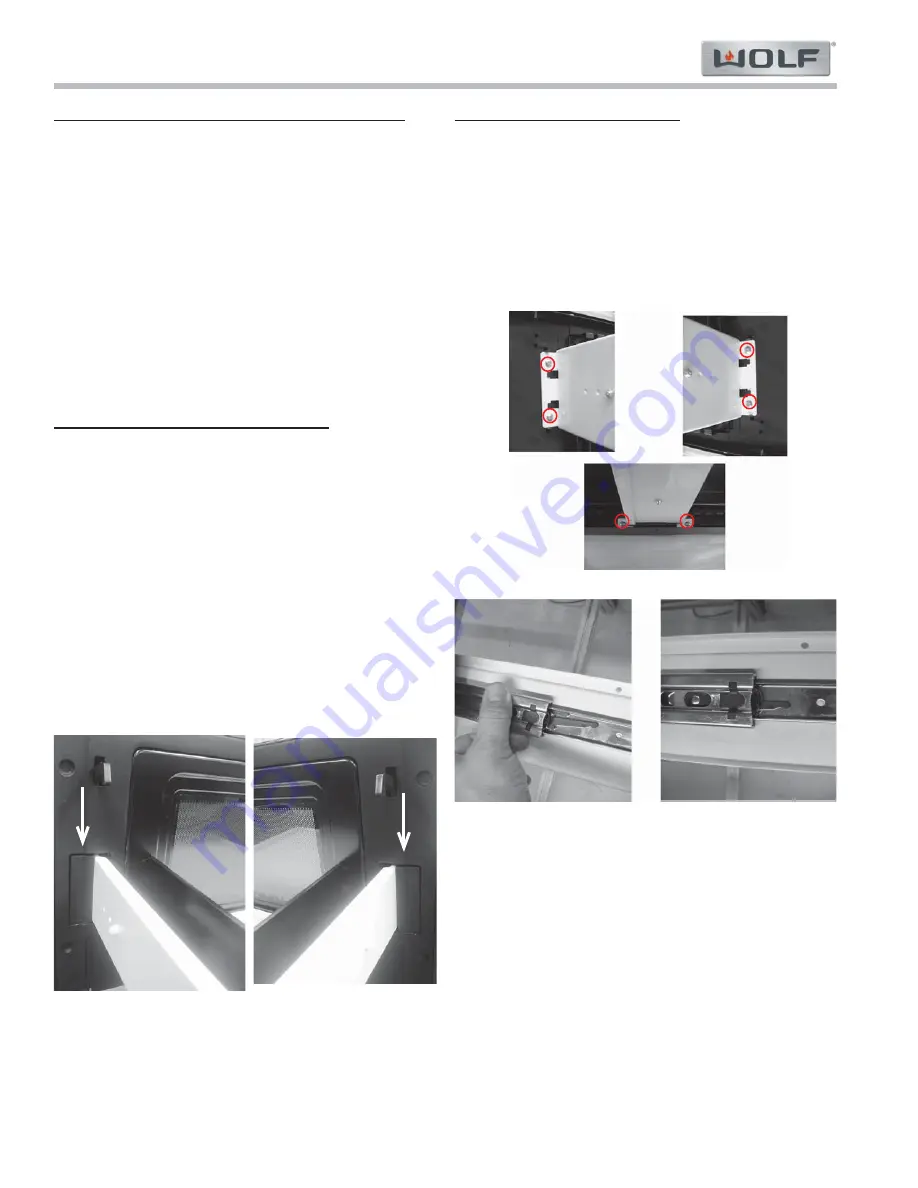
4.Remove two Drawer Support Covers from Choke
Cover
(See Figure 4-8)
.
5.Extract six screws from all three drawer Support
Angles.
(See Figure 4-9)
.
6.Unhook Drawer Support Angles from drawer, then
remove.
7.Door assembly is free and Choke Cover can be
removed by Inserting a putty knife (thickness of about
0.5mm) into gap between choke cover and door frame.
Carefully slide choke cover away from drawer as far
as possible.
Figure 4-8. Drawer Support Covers
Drawer Support Angle Removal
1.Remove Drawer Assembly and Choke Cover as stated
in prior section.
2.Extract two screws from right or left Drawer Support
Angles, then remove Angle assembly
(See Figure 4-
9)
.
3.Separate Slide Rails by moving inside lever of Slide
Rails. Slide Rail will now separate by pulling straight
forward and out.
(See Figure 4-10)
.
4.Drawer Support Angles or Slide Rails are now replace-
able.
Figure 4-9. Drawer Support Angles
Figure 4-10. Slide Rails


