background image


OPERATING MANUAL FOR SELECT EDI 60 


L300180 Iss:A 

28


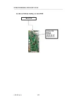
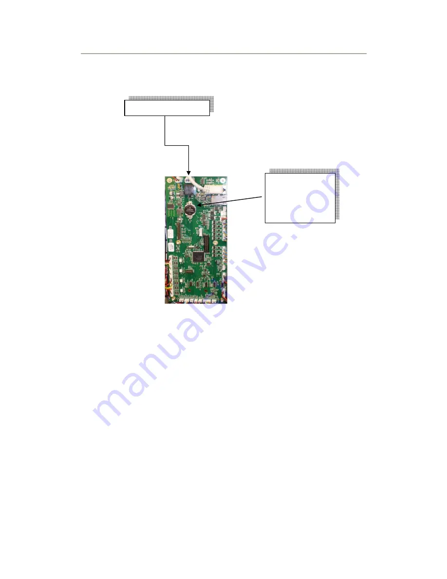
Location of lithium battery on main PCB 


Main PCB 

Lithium PCB 
battery                
Part No. 
(R083349) Ref 
Section 11.4.5 

Summary of Contents for L300180

Page 1: ...OPERATING MANUAL FOR SELECT EDI 60 Issue A L300180 1 SELECT EDI 60 Part No L300180 OPERATING MANUAL Issue A 10 03 17 ...

Page 2: ...uch screen display 10 5 2 2 Storage tank 10 5 2 3 Removable front cover 11 6 OPERATING YOUR WATER PURIFIER 12 6 1 Power on screen 12 6 2 Menu structure 13 6 3 Clean routine menu 13 6 4 Settings menu 13 6 4 1 Time and date 14 6 4 2 Alarms 15 6 4 3 Maintenance 17 6 4 4 Systems menu 18 6 4 5 Engineer menu 19 6 5 Factory Default settings 23 6 5 1 Setting menu defaults 23 6 5 2 System menu defaults 23 ...

Page 3: ...ecification 34 10 7 1 Feed water quality 34 10 7 2 Feed water pressures 34 10 8 Water services connections 35 10 9 Weights and dimensions 36 10 10 Environmental 36 10 11 Cartridge outputs 36 11 INSTALLATION 37 11 1 Unpacking 37 11 2 Installation Kit 37 11 3 Cartridge media pack 39 11 4 Unit positioning 39 11 4 1 Bench mounted 39 11 4 2 Wall mounted 40 11 5 Drain connection 42 12 APPENDIX 43 12 1 M...

Page 4: ...OPERATING MANUAL FOR SELECT EDI 60 L300180 Iss A 4 1 DOCUMENT HISTORY Issue Date of Change Description of Change Approved by A First Issue 10 03 2017 ...

Page 5: ...en before operating the unit Details on how to install commission your unit can be found in Section 12 Details on how to operate your unit can be found in Section 6 Details on how to maintain your unit can be found in Section 7 Warning Before operating the unit always check to see that the water and electrical connections are secure and not likely to cause a trip hazard If you have concerns about ...

Page 6: ...r Purification Systems Ltd Bandet Way Thame Oxfordshire OX9 3SJ United Kingdom Or your local distributor see www suezwater co uk for details For all spares consumable and general sales enquiries contact Customer Services Department Tel No 44 0 1844 217141 For all service enquiries contact Service Department Tel No 44 0 1844 211555 E mail mail waterpurificationsystems uk suez com Website www suezwa...

Page 7: ...ork should be completed by a trained competent person This symbol refers to a possibly hazardous situation Failure to observe these references may result in minor injuries and or damage to property I This symbol points out important information for working with the system in the proper manner Failure to observe these references may result in malfunctions in the system or impact on the environment ...

Page 8: ... must only be serviced and maintained by SUEZ Service personnel or SUEZ approved and trained technicians Failure to observe the instructions contained in this manual may compromise the safety performance and reliability of the unit and may void any warranties Under no circumstances try to service or repair the system yourself if you have not been trained and approved to do so 4 4 Operating staff O...

Page 9: ...osal 4 7 Unauthorised conversion and manufacturing replacement parts Modification of the unit is only permitted with the approval of the manufacturer The same applies to the uploading of new software for the control system Original replacement parts and accessories authorised by the manufacturer enhance safety the use of other non approved parts will void the warranty and could affect the safety a...

Page 10: ...C the output will decrease by as much as 3 per Degree C Refer to Section 11 1 for more details The Select edi 60 is supplied with an integral 20 litre tank or if larger storage is required additional 50 and 100 litre tanks are available Contact SUEZ sales department for details The unit type is detailed on its serial plate which can be found on the reverse side of the front cover The Select edi 60...

Page 11: ...ovable front cover The front cover is easily removed and provides access to the consumable cartridge media pack Use the two grab slots to gently pull away the front cover to gain access to the purification packs Bib Tap integral 20 litre tank Touch screen display ...

Page 12: ...ed to an electrical supply the unit goes through an initialisation process followed after 10 seconds by the Power On screen as shown above When the unit is started the RO Screen is displayed showing the condition of the permeate feed to the EDI module Pressing the NEXT button toggles between two further screens detailing the parameters around the EDI module and a general information screen showing...

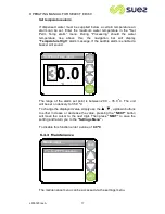
Page 13: ...em Menu Product Information Engineering menu Set Unit ID Auto Restart Set Log Frequency Data Logging 6 3 Clean routine menu Refer to Section 8 for details of disinfection procedure Selecting the Clean Routine from the menu begins the disinfection process Prompts are provided to guide you through the various stages of the disinfection process 6 4 Settings menu The settings menu enables system param...

Page 14: ...l number a confirmation screen will pop up stating Done and after a few seconds the screen will revert back to the Time Date Menu To select Set Date from the menu use the buttons and press ENTER The date will be displayed and the cursor will flash on the first number Use the buttons to change the number to the correct value then press NEXT to move to the next one On pressing NEXT on the final numb...

Page 15: ...r The unit will be supplied with the alarm buzzer Enabled The device can be programmed to activate alarms in the event that defined parameters are exceeded The alarms can be enabled to sound as an audible buzzer Audio alarm This is enabled disabled by first selecting the Audio alarm from the menu listing and then by simply touching the relevant box next to either Disabled or Enabled you can change...

Page 16: ... mimic screen will display Poor Water Quality alarm message If the audible alarm is enabled a buzzer will sound If the water quality improves to below the set point the alarm message will be removed from the screen and the buzzer will stop sounding The range of the alarm set point is between 15 25uS The unit will be set on delivery to 15uS Setting a value lower than 15uS will disable this alarm To...

Page 17: ...navigation bar will display Temperature High alarm message If the audible alarm is enabled a buzzer will sound The range of the alarm set point is between 20 0 35 0 o C The unit will be set on delivery to 35 0 o C To change the displayed value simply use the up down buttons to either increase or decrease the value pressing the NEXT button will move the cursor to the next digit Then press NEXT to s...

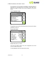
Page 18: ... 1067 20 10 16 0xCA8B 0xA619 1 02 The maintenance menu provides the capability to set defined dates for replacement of consumable items in the device These dates when expired will trigger an alarm which will be displayed on the mimic screen 6 4 4 Systems menu The systems menu provides information about your device and enables identifcation of the unit Product information Displays data about your d...

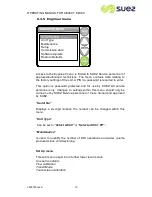
Page 19: ...This option is password protected and for use by SUEZ Ltd service personnel only Changes to settings within this menu should only be carried out by SUEZ Service personnel or those trained and approved by SUEZ Serial No Displays a six digit number the number can be changed within this menu Unit Type Can be set to Select edi 60 or Select edi 60 PP Maintenance Is used to quantify the number of EDI op...

Page 20: ...ts markers will cause the resulting values to be stored and used in place of the default values Default values will be entered used for Touch screen calibration whenever Commission Date This feature when selected will display the date on which the unit was commissioned The date is automatically entered following the setting of the time and date after Transit Mode If the unit is re commissioned at ...

Page 21: ... transfer for the Control board will likely take several minutes A indicator bar will be displayed providing an indication of rate of transfer Restore Defaults When this option is selected all the adjustable selectable options will revert back to their default settings Refer to Section 6 5 for a complete listing of factory default settings Set unit ID A discrete device identifier can be stored her...

Page 22: ...ata is written to the memory The frequency of sending data to the memory can be set via this menu option Data Logger Data can be downloaded and saved on a memory stick device and transferred to a PC computer Refer to Section for details of suitable memory devices Upload files Follow the displayed commands to download data from the unit memory Insert data stick into the USB port on the underside of...

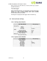
Page 23: ...cepting clear data logger clears the data file log 6 5 Factory Default settings 6 5 1 Setting menu defaults SETTINGS MENU Default settings Date and Time Set Time Set Date Set Format DD MM YY Alarms Audio Alarm Enable Enable Permeate Quality Alarm 15 uS Permeate Temperature Alarm 35 o C Rinse Temperature 30 C Maintenance Pre treat PT Pack date 6 5 2 System menu defaults SYSTEM MENU Default settings...

Page 24: ... Type Select edi 60 Select edi 60 PP Maintenance EDI Run Hours EDI On Offs Total Volume Setup Line Cell Constants Outlet Line Cell 0 12 Product Line Cell 0 13 RO Line Cell 0 55 Flow Calibration 16000 Transit Mode Disabled Touchscreen Calibration Commission Date Software Update Update Display Update Controller Update GUI Restore Defaults ...

Page 25: ...he cartridge to be replaced and pull it away from its retainer block Discard the media pack and remove the new pack from its packaging ensuring that the two plugs are removed from the inlet outlet ports Slide the media pack into the retaining block push it home until it clicks into position and retaining mechanism clicks up and locks Check by trying to pull the cartridge it should not slide back o...

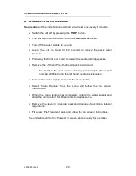
Page 26: ...re momentarily switch the unit on then off Remove the right hand side panel of the unit o To do so first remove the front cover by pulling it gently from the unit using the hand holds provided o Pull the pod assembly gently forward to disengage the top cover retaining pin o Remove the top cover by lifting up the front and sliding gently backwards o Remove the four retaining screws holding the side...

Page 27: ...over 5 Pull the Pod forward to disengage from the top cover The top cover can then be lifted away from the unit Once removed the battery can be clearly seen on the main PCB prise the battery out of its holder Refer to location Lithium battery on main PCB diagram 7 Refit the new battery ensuring the positive side is facing upwards the battery should be pressed gently until the four clamps in the re...

Page 28: ...OPERATING MANUAL FOR SELECT EDI 60 L300180 Iss A 28 Location of lithium battery on main PCB Main PCB Lithium PCB battery Part No R083349 Ref Section 11 4 5 ...

Page 29: ...ks Remove the left hand Pre Treatment pack and discard o To sanitise the unit insert a cleaning pack adaptor Suez part number L998549 into the left hand media pack location Turn on the water supply and press the menu button Select Clean Routine from the menu and follow the on screen instructions When the clean routine has completed isolate the water supply and allow the unit to stand for 60 second...

Page 30: ... Select edi 60 membrane degasser ELECTRO DEIONISATION CELL R090330 Select edi 60 cell INSTALLATION WALL MOUNTS L300901 wall mount kit PM00901 Installation kit L991110 Feed water pressure regulator L998405 External Tank Wall mount Kit EXTERNAL FILTRATION L991276 10 filter housing R011044 10 5µm filter element OTHERS L998549 Disinfection pack R041180 Operator s Manual extra copies R083349 Main PCB B...

Page 31: ...2 2 Check all replacement dates and replace where necessary 3 Contact supplier with details 4 Check condition of pre filter 10 2 Alarm Warning messages DISPLAY POSSIBLE CAUSE OPERATOR ACTION TEMPERATURE SENSOR ERROR Temperature probe lead possibly disconnected or faulty Contact your local distributor or SUEZ Service Department LINE CELL ERROR Line cell lead possibly disconnected or faulty Contact ...

Page 32: ...required Contact supplier if new pack does not improve water quality TANK LOW LEVEL Water in process tank below low level Usage exceeding make up rate Check feed water supply and RO performance Check tank level visual Check take off rate from any attached equipment eg Washers COMMS ERROR Link between keypad and main PCB faulty Contact your local distributor or SUEZ service department TEMPERATURE H...

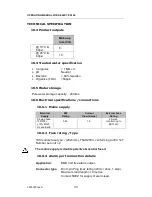
Page 33: ... connections 10 6 1 Mains supply Electrical Supply KW Rating Current Draw Amps External Fuse Rating Single phase 100 230v 10 50 60 Hz and Earth 0 25 1 0 5 Amps conforming to BS1362 10 6 2 Fuse rating type IEC module fuse type 20x5mm T5AH250V conforming to IEC 127 Number per unit 2 The mains supply is double pole live neutral fused 10 6 3 Alarm port connection details Application BMS Volt free alar...

Page 34: ...ater intended for human consumption but with the following additions Pre Filtration Filtered to 5 Micron Free Chlorine 1 ppm as Cl2 Total Dissolved Solids Max 1000 ppm Temperature 1 35 o C 33 8 95 o F TOC Up to 2000ppb Typical Provided by external filter assembly supplied as part of the installation kit 10 7 2 Feed water pressures Feed water Pressure Max 90 psi Feed water Pressure Min 20 psi Optim...

Page 35: ...the unit Using the installation kit provided attach the water feed Low pressure drain high pressure drain and overflow tubing as shown below Unit Viewed from the rear Electrical hydraulic connections Dry alarm contact External tank connection Main voltage supply Overflow Rear tank outlet Feed water Low pressure drain High pressure drain ...

Page 36: ...ive Humidity 30 to 80 Max Altitude 2000m Transport and Storage temperature limited by RO membranes 5 to 85 o C with frost protection liquid 40 to 85 o C RFI EMI Radiation Care must be taken not to have sources of RFI EMI which are liable to cause electromagnetic disturbance to the unit If the unit is affected by such disturbances the sources should be suppressed or relocated 10 11 Cartridge output...

Page 37: ...ls on how to install the wall mounting kit 11 1 Unpacking Remove all packaging materials and ensure the following items have been provided Select edi 60 unit Installation kit Select wall mount kit optional 1 off PT media pack 1 off Flushing pack User manual 11 2 Installation Kit The installation kit comprises of the following items 1 off security clips 1 off 12mm stem elbow 3 off 8mm stem elbow 3 ...

Page 38: ...OPERATING MANUAL FOR SELECT EDI 60 L300180 Iss A 38 ...

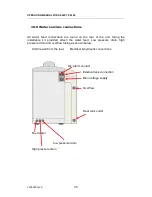
Page 39: ...nd position Refer to Section 9 Consumables for part nos of all consummable items 11 4 Unit positioning The Select edi 60 can be either bench or wall mounted 11 4 1 Bench mounted Locate the unit on a suitable work surface ensuring access to tank dispense bib tap and sufficient clearance to rear of the machine for all water and electrical connections All water feed connections are found on the rear ...

Page 40: ...k the centre fixing position on the wall allowing for the height of the unit below the ceiling level 650mm min Drill the centre fixing hole to the correct size for the masonry fastener to be used and install the first fastener Offer the main bracket body to the wall and fix tightly to the wall after levelling the bracket and mark the remainder of the fixing positions Remove the bracket from the wa...

Page 41: ...e underside of the unit and discard the feet and fixing screws Slide the base plate onto the main wall bracket ensuring it is fully back Lift the unit onto the base plate and fit the two shorter Anulok retaining screws through the front of the slide plate into the unit feet inserts Fit the longer Anulok retaining screws through the base plate rear fixing positions slots and into the water unit rea...

Page 42: ...te trap the unit to the main bracket and stop the unit from moving sideways 11 5 Drain connection Attach a suitable length of 8mm tubing to both drain connections so that the free end may be inserted into an appropriate drain The tubing must not be kinked or the flow restricted in any way If the drain is to be run over 5 metres and or rises above the level of the unit then contact our Service Depa...

Page 43: ...SELECT EDI 60 L300180 Iss A 43 12APPENDIX 12 1 MSDS Material Safety Data Sheets for the following accessories are available upon request or can be downloaded from the SUEZ web site see Section 3 for details PT 8 Media Pack ...

Page 44: ...y hand an integral collet locking system then holds the tube firmly in place without deforming it or restricting flow Cut the tube square and push in until the tube stops Fitting grips before it seals Ensure tube is pushed into tube stop securing tube in position To remove tubing push collet against body and slide tube out of fitting ...

Page 45: ...d concentrate The concentrate is pumped at high velocity across the RO membrane to lessen the risk of fouling or scaling The concentrate flow rate is controlled by a fixed orifice restrictor located in the drain line The permeate is further purified by the second reverse osmosis membrane with the concentrate returning to the pump inlet for recirculation The second stage permeate then flows through...

Page 46: ...OPERATING MANUAL FOR SELECT EDI 60 L300180 Iss A 46 L300180 PID 1 1 1 0 4Bar 15l h 3 bar 18L h 7 bar 0 5 Bar inlet 80L h pump 0 3 ID 40lg 0 9 ID ...

Page 47: ...OPERATING MANUAL FOR SELECT EDI 60 L300180 Iss A 47 12 4 CE declaration A copy of Declaration of Conformity can be obtained from SUEZ upon request or from our website at www suezwater co uk ...

Page 48: ... 0844 873 1034 E mail info complydirect com Fax No 0844 873 1035 SUEZ Registration No WEE EGO267RW Users in other European Countries should contact their producer who will be the organisation in their country that supplied the product For users outside of the European Union if you wish to discard this product then please contact your local authorities or dealer and ask for the correct method of di...

Reviews: