


2
No.
①
②
③
④
⑤
Name
Upper track
for soft-closing
(surface mount)
Upper track
for soft-closing
(recessed mount)
Upper track for
standard sliding
(surface mount)
Upper track for
standard sliding
(recessed mount)
Soft closer
(two-way)
Trigger, Jig
Upper roller
Item No.
FD35EV-TRM-SC FD35EV-TRH-SC
FD35EV-TRM
FD35EV-TRH
FD35EV-WRH-DSC
FD35EV-TRG
FD35EV-TRJ
FD35EV-WRH-N
Item
Flat head tapping screw
3.8×40
・・・・・・・
3 pcs
Countersunk head tapping screw
4×30
・・・・・・・・・
2 pcs
Flat head tapping screw
3.8×40
・・・・・・・
3 pcs
Accessories
Hole pitch
:
300 mm
Pitch end
:
30 mm
Recommended screw:Countersunk head tapping screw 3.5×25
Use the track for standard sliding for inline sliding
Hole pitch
:
300 mm
Pitch end
:
30 mm
Recommended screw:Countersunk head tapping screw 3.5×25
Single sliding
either one
−
1 pc
1 pc
1 pc
Double sliding
either one
−
2 pcs
2 pcs
2 pcs
In line sliding
−
either one
2 pcs
2 pcs
2 pcs
No.
⑥
⑦
⑧
⑨
⑩
⑪
⑫
Name
Floor guide
Bumper block
Trigger
Door guide track
Cover cap
Door stopper
Spanner
wrench
Item No.
FD50-BGR18
FD35EV-HBB
FD35EV-TRG
FD30-HBRT1500SIL
FD50-WRH-CP
FD30-HTKY
FD30-FSP
Item
Thickness: 2 mm
Bind head tapping screw
4×30
・・・・・・・・・
3 pcs
Hole pitch
:
250 mm
Pitch end
:
30 mm
Recommended screw:
Countersunk head tapping screw 4×20
Countersunk head tapping screw
4×20
・・・・・・・・・・・・・・・・・・
4 pcs
Single sliding
1 pc
−
−
1 pc
2 pcs
−
−
Double sliding
2 pcs
−
−
2 pcs
4 pcs
−
−
In line sliding
2 pcs
1 pc
2 pcs
2 pcs
4 pcs
−
−
Trigger
Nut
Trigger
Trigger
Jig
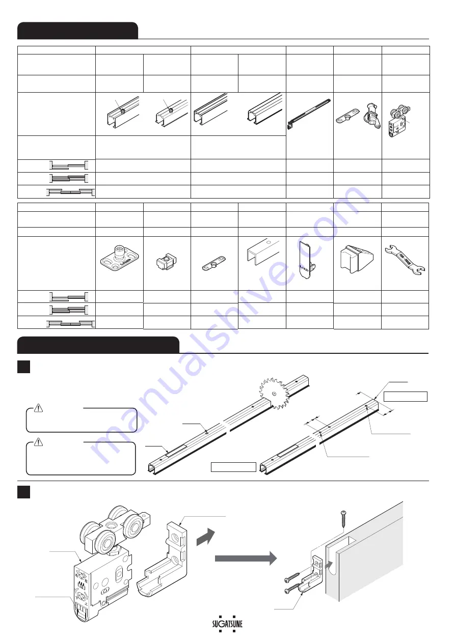
COMPONENT PARTS
This describes installation of a single sliding door.
INSTALLATION PROCEDURE
1
Cutting Track and Hole Drilling on Upper track
The method of calculating the trigger mounting
position is described on the last page of Appendix 4.
(
In this manual, a single sliding door is used as an example.
)
Preparation of Mounting Parts
2
Do not cut trigger side (with sticker)
of upper track.
When cutting, reinforce the track
to prevent deformation at the cut
section.
CAUTION
CAUTION
Casing
Hole drilling
Cutting
Sticker
Trigger
Cut end
2×
I
4.5
(for trigger fixing)
※
2
[ ]: When Cover cap
⑩
(option) is used.
I
4.5
I
7.8 CSK
(for track fixing)
30
Door width - 376
[Door width - 378 ]
※
2
30
Leading edge
Trailing edge
❶
❷
Main unit
Pull out casing
Pull up lever


