background image

7

361 [363]

3

30

361 [363]

3

187.5

Door width

Available opening width

187.5

Available opening width

Door width

30

30

Door stopper

(Option)

! 

! 

Door stops here when closed.

Door must be stopped by 
bumper block and door stopper.

Door must be stopped by 
bumper block and door stopper.

Door stopper

(Option)

Trigger

Trigger

Leading edge when the 
door is fully opened

Crimped trigger

Door stops here when opened.

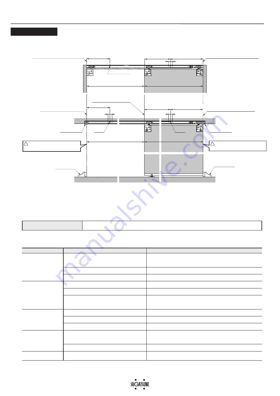
Standard installation

Upper track installed inside door jamb

Bumper block

(Option)

3

 [  ] : When cover cap 

  (option) is used.

Door width - 361

[Door width - 363]

3

Door width - 361

[Door width - 363]

3

Bumper block

(Option)

Reference line for trailing edge.
(Trailing edge when the door is opened.)

Reference line for leading edge.
(Leading edge when the door is stopped.)

Special fit

(e.g.) No vertical frame and 
stop with door stopper and 
bumper block

Trouble

Checkpoint

Solution

Door stops during soft 
closing

&KHFNLIGRRUERWWRPFRQWDFWVZLWKÀRRU

&RQ¿UPWKDWWUDFN¿[LQJVFUHZVDUHQRWORRVHQHG7KHQDGMXVWGRRUKHLJKW
VXFKWKDWWKHFOHDUDQFHEHWZHHQWKHGRRUERWWRPDQGÀRRULVPP

Check if upper track is set horizontally.

Using a level gauge, reset upper track horizontally.

Check if mohair seal is installed.

Reduce the friction between mohair and door.

No soft closing

Check if trigger is installed.

Install trigger to correct position.

Check if door is closed by excessive force.

Do not close door by excessive force as it may damage soft closer.

The position of the trigger catcher may become 
dislocated (See section .) 

Slowly move the door toward the leading edge, then push the door firmly. 
Repeat this action on the opposite side as well.
If it is still not improved, check the status of the trigger catcher in section  .

Abnormal noise during 
operation

Check if door touches other parts.

Provide necessary space between the door and adjacent objects.

Check track rollers for aluminum dust.

Remove the track and pull out the roller. Then, clean the roller.

Check for loose screws retaining the upper track.

Tighten the screw.

Heavy door operation

Check if door touches adjacent parts.

Correct door position to avoid contact with other objects.

$GMXVWSRVLWLRQRIÀRRUJXLGHRUVWRSSHU

Check if the door is warped.

Replace door with one that is not warped.

Door does not move.

Check the track retaining screws for looseness.

Retighten screws to free the roller.

Ŷ7528%/(6+227,1*

Trigger positions

APPENDIX 4

PERIODICAL INSPECTION

Clean the inside of the track.

Check the upper and lower space of the door. If necessary, correct the space.

Check the upper and lower space of the door. If necessary, correct the space.

Summary of Contents for LAMP FD35EV

Page 1: ...g of symbols WARNING If not followed death or serious injury may result Caution If not followed injury or damage may result 7KLV SURGXFW VKRXOG EH LQVWDOOHG E D TXDOL HG SHUVRQ LQ DFFRUGDQFH ZLWK WKLV PDQXDO I LW LV QRW LQVWDOOHG FRUUHFWO WKH GRRU may fall and cause injury 3URYLGH D IUDPH WKDW FDQ ZLWKVWDQG WKH ZHLJKW DQG LPSDFW RI RSHQLQJ DQG FORVLQJ WKH GRRU H VXUH WR XVH WKH VSHFL HG VFUHZV DQG...

Page 2: ...h Item No FD50 BGR18 FD35EV HBB FD35EV TRG FD30 HBRT1500SIL FD50 WRH CP FD30 HTKY FD30 FSP Item Thickness 2 mm Bind head tapping screw 4 30 3 pcs Hole pitch 250 mm Pitch end 30 mm Recommended screw Countersunk head tapping screw4 20 Countersunk head tapping screw 4 20 4 pcs Single sliding 1 pc 1 pc 2 pcs Double sliding 2 pcs 2 pcs 4 pcs In line sliding 2 pcs 1 pc 2 pcs 2 pcs 4 pcs Trigger Nut Trig...

Page 3: ...ert the parts in order from to with care of direction 1 2 Remove any dirt or aluminum chips from the track Tape around rollers and upper track to prevent the inserted parts from falling CAUTION LWKRXW YHUL FDWLRQ WKH VHOI FORVLQJ IHDWXUH PD IDLO CAUTION Soft closer 1 2 Upper track Sticker Cut end Upper roller Leading edge Trailing edge Correct set position Improper set position Trigger catcher Red...

Page 4: ... groove under the door RQ WKH SURWUXGLQJ SDUW RI WKH ÀRRU JXLGH Support 10mm To be removed after hanging protruding part Floor guide Lever Casing Main unit CLICK Floor guide 44 18 7 Mounting of Floor Guide Temporarily Hanging Door 8 3RVLWLRQ ÀRRU JXLGH MXVW EHORZ WKH FHQWHU RI WKH upper track Temporarily fasten through the slotted holes with the provided screws 9HUL FDWLRQ RI 6RIW ORVHU 2SHUDWLRQ ...

Page 5: ...ith the provided spanner until it contacts the soft closer Be sure to tighten the nut to prevent damage CAUTION Adjusting Fastening the Floor Guide 10 If the door movement is not smooth remove the door then adjust the floor guide forwards or backwards Adjustment range 4 mm Do not turn the adjustment screw beyond adjustment range CAUTION Do not turn adjustment screw beyond adjustment range Do not u...

Page 6: ... Spanner wrench Lever APPENDIX 1 Use a 10 mm support under the door Then pull out the upper roller main unit from the door while raising the lever It will be easier if you slide the hanger bolt with a spanner Be careful not to let the door fall CAUTION Bumper block Sold seperaterly Bumper block Sold seperaterly Door stopper Option Door stopper Option Min 13 Min 13 APPENDIX 2 When vertical frame is...

Page 7: ...duce the friction between mohair and door No soft closing Check if trigger is installed Install trigger to correct position Check if door is closed by excessive force Do not close door by excessive force as it may damage soft closer The position of the trigger catcher may become dislocated See section Slowly move the door toward the leading edge then push the door firmly Repeat this action on the ...

Page 8: ...ail sales sugatsune com Chicago USA Phone 1 312 461 1081 E mail chicagoshowroom sugatsune com SUGATSUNE CANADA INC Phone 1 514 312 5267 E mail support sugatsune ca 2020 12 0963 3 INSTALLATION DRAWING EXAMPLE In this manual a single sliding door is used as an example 3 When using cover cap When using door guide track Door process dimensions See P 6 APPENDIX 2 when door stopper option is used CAUTIO...

Reviews: