10
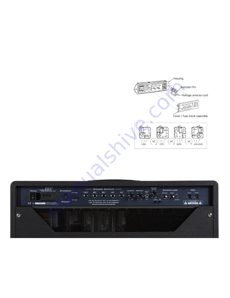
EX.1
TUBES
The PT-100 tube complement consists of four EL-34 power tubes and six 12AX7
preamp tubes.
PREAMP TUBE POSITION LIST
V1 (closest to the input jack) First gain stage for Channel 1 and 2
V2 Additional gain stages for Channel 1
V3 Additional gain stage for Channel 2 / 3
V4 Additional gain stage for Channel 2 / 3 and it’s tone stack
V5 Effects loop
V6 Phase inverter
FUSE AND VOLTAGE SELECTION
Voltage selection is made externally at the Power Entry Module. See diagram EX. 1
Open cover using small blade screwdriver or similar tool. Set aside cover/fuse block
assembly. Pull voltage selector card straight out of housing using an indicator pin,
orient selector card so that the desired voltage is readable at the bottom (see below).
Fix indicator pin into notch at opposite side. Insert voltage selector card into housing,
printed side of card facing towards on/off switch and edge containing the desired
voltage first. Replace cover and verify that the indicator pin shows the desired voltage
on the cover assembly.
Troubleshooting Notes:
• If the amplifiers lights operate but there is no sound, we recommend checking/
replacing the HT fuse.
• If there are no lights, or sound, we recommend checking/replacing the Mains fuse
which can be found behind the Fuse Block Assembly Plate.


