Section 2
DESCRIPTION
8
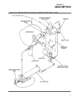
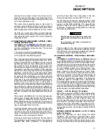
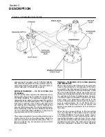
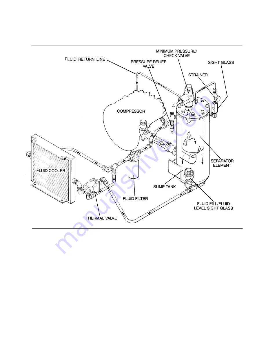
Figure 2---4 Compressor Discharge/Cooling and Lubrication System (Air---Cooled)
Sullair recommends that a 24KT sample be taken
at the first filter change and sent to the factory for
analysis. This is a free service. The sample kit with
instruction and self addressed container is sup-
plied with your compressor. The user will receive an
analysis report with recommendations.
For the water---cooled models, a shell and tube
heat exchanger and water---flow regulating valve
are substituted for the radiator---type cooler and
cooler bypass valve listed above.
The pressure in the receiver/sump causes fluid flow
by forcing the fluid from the high pressure area of
the sump to an area of lower pressure in the com-
pressor unit.
On air---cooled models, the fluid flows from the bot-
tom of the receiver/sump to the thermal valve. The
thermal valve has a nominal temperature of 170
_
F
(77
_
C). At low temperatures, the fluid passes
through the thermal valve, the filter and directly to
the compressor unit.
As the discharge temperature rises above 170
_
F
(77
_
C), due to the heat of compression, the ther-
mal valve begins to close and a portion of the fluid
then flows through the cooler; from the cooler to the
filter, and on to the compressor unit.
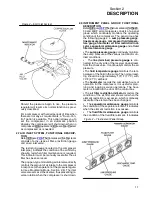
On water---cooled models, a water---flow regulating
valve will regulate the amount of cooling necessary
to maintain the proper operating temperature.
When the fluid leaves the sump it is directed to the
cooler. Depending on the temperature of the fluid,
the water---flow regulating valve allows the proper
Summary of Contents for 10B 25HP
Page 2: ...NOTE For Additional Information on 24KT Units See Inside Back Cover...
Page 4: ...NOTES...
Page 22: ...16 NOTES...
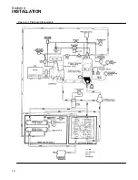
Page 24: ...Section 4 INSTALLATION 18 Figure 4 1 Piping and Instruments...
Page 26: ...20 NOTES...
Page 42: ...36 NOTES...
Page 44: ...NOTES...
Page 45: ......


