Section 6
MAINTENANCE
25
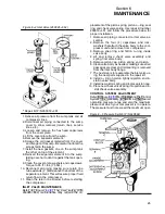
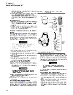
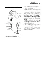
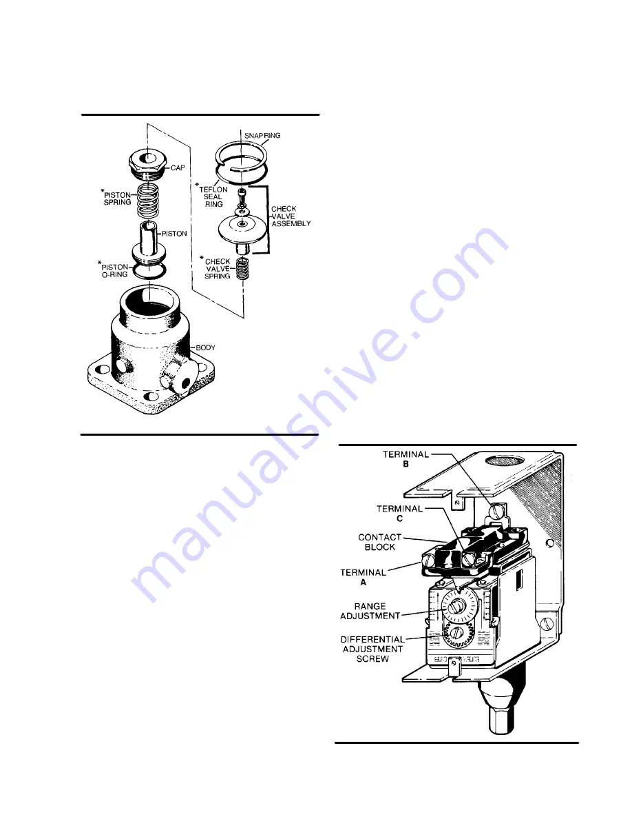
Figure 6---4 Inlet Valve (250025---654)
* Repair Kit P/N 250019---451
1. Relieve all pressure from the sump tank and all
compressor lines.
2. Disconnect all piping connected to the sump
cover to allow removal (return lines, service
lines, etc.).
3. Loosen and remove the hex head capscrews
from the cover plate.
4. Lift the cover plate from the sump.
5. Remove the separator element.
6. Scrape the old gasket material from the cover
and flange on the sump. Be careful not to let the
scraps fall in the sump.
7. Install the new gaskets; one on the sump tank
the other on top of the element.
8. Reinsert the separator element into the sump
taking care not to dent it against the tank open-
ing.
9. Clean the cover plate, washers and capscrews.
Torque to 55 ft.---lbs. (75 Nm).
10. Reconnect all piping making sure return line
tube extends
!
@
4
” (6mm)above the bottom of the
separator element. This will assure proper fluid
return flow to the compressor.
11. Clean the return line strainer before restarting
the compressor.
INLET VALVE MAINTENANCE
. The inlet va lve (P/ N
250025---654) maintenance may require the re-
placement of the piston spring, piston o---ring, seal
ring, and check valve spring. Use repair kit number
250019---451 and follow the procedure below for
proper installation.
1. Remove all piping connected to inlet valve as-
sembly.
2. Remove the four (4) capscrews and lock-
washers that attach the valve body to the com-
pressor unit and remove from compressor.
3. Remove snap ring and Teflon o---ring inside
valve body.
4. Lift and remove check valve assembly and
spring from valve body.
5. Remove piston cap, piston spring, and piston.
6. Clean valve body as needed, making sure all air
passages are clear and old seal ring is removed
from the inlet body flange.
7. The next step is to reassemble the inlet valve us-
ing the new parts supplied in the repair kit.
8. Install o---ring on piston, lightly oil piston, and in-
stall in valve body.
9. Install new piston spring and replace piston cap.
10. Place new check valve spring into piston and in-
stall check valve assembly
CONTROL SYSTEM ADJUSTMENT
. Prior t o a dj usting the Control
System, it is necessary to determine t he desired
operating pressure range and also the maximum
pressure at which your compressor is to operate.
The pressure must not exceed the maximum oper-
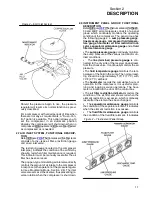
Figure 6---5 Pressure Switch (P/N 040694)
Summary of Contents for 10B 25HP
Page 2: ...NOTE For Additional Information on 24KT Units See Inside Back Cover...
Page 4: ...NOTES...
Page 22: ...16 NOTES...
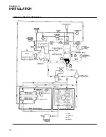
Page 24: ...Section 4 INSTALLATION 18 Figure 4 1 Piping and Instruments...
Page 26: ...20 NOTES...
Page 42: ...36 NOTES...
Page 44: ...NOTES...
Page 45: ......

