Section 1
SAFETY
7
antifreeze compound enters the eyes or if fumes
irritate the eyes, they should be washed with large
quantities of clean water for 15 minutes. A physi-
cian, preferably any eye specialist, should be con-
tacted immediately.
K. DO NOT
store ether cylinders or air line anti-icer
system antifreeze compound in operator’s cabs or
in other similar confined areas.
L.
The antifreeze compound used in air line anti-
icer systems contains methanol and is toxic, harm-
ful or fatal if swallowed. Avoid contact with the skin
or eyes and avoid breathing the fumes. If swal-
lowed, induce vomiting by administering a table-
spoon of salt in each glass of clean warm water
until vomit is clear, then administer two tablespoons
of baking soda in a glass of clean water. Have
patient lay down and cover eyes to exclude light.
Call a physician immediately.
1.8 ELECTRICAL SHOCK
A.
Keep the towing vehicle or equipment carrier,
compressor hoses, tools and all personnel at least
10 feet (3 meters) from power lines and buried
cables.
B.
Keep all parts of the body and any hand-held
tools or other conductive objects away from
exposed live parts of electrical system. Maintain dry
footing, stand on insulating surfaces and DO NOT
contact any other portion of the compressor when
making adjustments or repairs to exposed live parts
of the electrical system.
C.
Attempt repairs only in clean, dry and well- light-
ed and ventilated areas.
D.
Stay clear of the compressor during electrical
storms! It can attract lightning.
1.9 LIFTING
A.
If the compressor is provided with a lifting bail,
then lift by the bail provided. If no bail is provided,
then lift by sling. Compressors to be air lifted by hel-
icopter must not be supported by the lifting bail, but
by slings instead. In any event, lift only in full com-
pliance with OSHA Standards 29 CFR 1910 subpart
N or any other Local, State, Military and Federal
regulations that may apply.
B.
Inspect lifting bail and points of attachment for
cracked welds and for cracked, bent, corroded or
otherwise degraded members and for loose bolts or
nuts prior to lifting.
C.
Make sure entire lifting, rigging and supporting
structure has been inspected, is in good condition
and has a rated capacity of at least the net weight
of the compressor plus an additional 10%
allowance for weight of snow, ice, mud or stored
tools and equipment. If your are unsure of the
weight, then weigh compressor before lifting.
D.
Make sure lifting hook has a functional safety
latch or equivalent, and is fully engaged and latched
on the bail.
E.
Use guide ropes or equivalent to prevent twisting
or swinging of the compressor once it has been lift-
ed clear of the ground.
F. DO NOT
attempt to lift in high winds.
G.
Keep all personnel out from under and away
from the compressor whenever it is suspended.
H.
Lift compressor no higher than necessary.
I.
Keep lift operator in constant attendance whenev-
er compressor is suspended.
J.
Set compressor down only on a level surface
capable of supporting at least its net weight plus an
additional 10% allowance for the weight of snow,
ice, mud or stored tools and equipment.
K.
If the compressor is provided with parking
brakes, make sure they are set, and in any event,
block or chock both sides of all running wheels
before disengaging the lifting hook.
1.10 ENTRAPMENT
A.
Make sure all personnel are out compressor
before closing and latching enclosure doors.
B.
If the compressor is large enough to hold a man
and if it is necessary to enter it to perform service
adjustments, inform other personnel before doing
so, or else secure the access door in the open posi-
tion to avoid the possibility of others closing and
possibly latching the door with personnel inside.
1.11 JUMP STARTING
A.
Observe all safety precautions mentioned else-
where in this manual.
B.
Batteries may contain hydrogen gas which is
flammable and explosive. Keep flames, sparks and
other sources of ignition away.
C.
Batteries contain acid which is corrosive and poi-
sonous.
DO NOT
allow battery acid to contact
eyes, skin, fabrics or painted surfaces as serious
personal injury or property damage could result.
Flush any contacted areas thoroughly with water
immediately. Always wear an acid-resistant apron
and face shield when attempting to jump start the
compressor.
D.
Remove all vent caps (if so equipped) from the
battery or batteries in the compressor.
DO NOT
per-
mit dirt or foreign matter to enter the open cells.
Summary of Contents for 1350XH
Page 6: ......
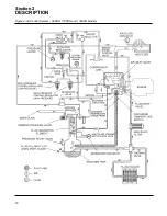
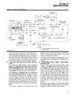
Page 18: ...Section 2 DESCRIPTION 12 Figure 2 3A Control System 900XH 1150XH and 1350XH Models...
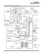
Page 19: ...Section 2 DESCRIPTION 13 Figure 2 3B Control System Aftercooled Models...
Page 29: ...Section 2 DESCRIPTION 23 Figure 2 7 Wiring Diagram 02250145 161R01...
Page 30: ...NOTES 24...
Page 33: ...Section 3 SPECIFICATIONS 27 02250135 977R03 Figure 3 2 Identification Compressor Assembly...
Page 34: ...NOTES 28...
Page 38: ...NOTES 32...
Page 54: ...Section 7 ILLUSTRATIONS AND PARTS 48 02250127 622R08 7 3 ENGINE AND COMPRESSOR MOUNTING...
Page 56: ...Section 7 ILLUSTRATIONS AND PARTS 50 02250127 622R08 7 3 ENGINE AND COMPRESSOR MOUNTING...
Page 58: ...Section 7 ILLUSTRATIONS AND PARTS 52 02250136 060R02 7 4 AIR INLET SYSTEM ALL MODELS...
Page 60: ...Section 7 ILLUSTRATIONS AND PARTS 54 02250136 060R02 7 4 AIR INLET SYSTEM ALL MODELS...
Page 62: ...Section 7 ILLUSTRATIONS AND PARTS 56 02250136 062R02 7 5 EXHAUST SYSTEM ALL MODELS...
Page 72: ...Section 7 ILLUSTRATIONS AND PARTS 66 02250127 633R02 7 7 ENGINE RADIATOR ASSEMBLY ALL MODELS...
Page 74: ...Section 7 ILLUSTRATIONS AND PARTS 68 7 8 AFTERCOOLER MOUNTING ALL MODELS 02250150 135R03...
Page 82: ...Section 7 ILLUSTRATIONS AND PARTS 76 02250140 983R01 7 12A INLET VALVE AND PARTS 6 5 900XH...
Page 86: ...Section 7 ILLUSTRATIONS AND PARTS 80 02250054 762R06 7 13A INLET VALVE PARTS 6 5 900XH...
Page 90: ...Section 7 ILLUSTRATIONS AND PARTS 84 02250127 667R10 7 14A DISCHARGE SYSTEM 900XH AND 1150XH...
Page 96: ...Section 7 ILLUSTRATIONS AND PARTS 90 02250148 288R01 7 14C DISCHARGE SYSTEM 1350XH AFTERCOOLED...
Page 98: ...Section 7 ILLUSTRATIONS AND PARTS 92 02250148 288R01 7 14C DISCHARGE SYSTEM 1350XH AFTERCOOLED...
Page 116: ...Section 7 ILLUSTRATIONS AND PARTS 110 02250164 870R01 7 19 MINIMUM PRESSURE CHECK VALVE...
Page 118: ...Section 7 ILLUSTRATIONS AND PARTS 112 02250136 066R00 7 20 FUEL SYSTEM AND PARTS ALL MODELS...
Page 120: ...Section 7 ILLUSTRATIONS AND PARTS 114 02250127 727R01 7 21 ELECTRICAL PARTS ALL MODELS...
Page 126: ...Section 7 ILLUSTRATIONS AND PARTS 120 02250136 503R02 7 23 FRAME AND PARTS...
Page 128: ...Section 7 ILLUSTRATIONS AND PARTS 122 7 24 DECAL GROUP...
Page 130: ...Section 7 ILLUSTRATIONS AND PARTS 124 7 24 DECAL GROUP...
Page 132: ...Section 7 ILLUSTRATIONS AND PARTS 126 7 24 DECAL GROUP...
Page 134: ...Section 7 ILLUSTRATIONS AND PARTS 128 7 24 DECAL GROUP...
Page 136: ...Section 7 ILLUSTRATIONS AND PARTS 130 7 25 DECAL LOCATIONS 02250136 067R03...
Page 138: ...Section 7 ILLUSTRATIONS AND PARTS 132 7 25 DECAL LOCATIONS 02250136 067R03...
Page 140: ...NOTES 134...
Page 141: ......


