Section 2
DESCRIPTION
10
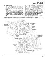
blies of the Sullair 900XH-1350XH Open Frame Air
Compressors models are clearly shown. The pack-
age includes a
compressor unit
,
diesel engine
,
compressor inlet system
,
compressor cooling
and lubrication system
,
compressor discharge
system
,
capacity control system
,
instrument
panel
and
electrical system
. The Sullair com-
pressor unit is driven by an industrial engine
designed to provide enough horsepower for more
than adequate reserve at rated conditions. Refer to
Engine Operator's Manual for a more detailed
description of the engine.
The
engine cooling system
is comprised of a
radiator
,
high capacity fan
and
thermostats
. The
high capacity fan draws air through the radiator,
keeping the engine at the proper operating temper-
ature.
The same fan also cools the fluid in the compressor
cooling and lubrication system. Prior to passing
through the radiator, the fan air also passes through
the compressor fluid cooler (which is mounted adja-
cent to the radiator). As air passes through the
cooler, the heat of compression is removed from the
fluid.
The same fan also cools the engines intake air sup-
ply. Prior to passing through the radiator and oil
cooler, the fan air passes through an air to air after-
cooler. As air passes through the air to air after-
cooler heat is removed which was introduced by the
engine's turbo charger. The engine is coupled to
the compressor unit with a non-lubricated vulcan-
ized rubber disc and drive flange-type coupling.
On open frame compressors supplied without fuel
tanks, the customer is responsible for providing
fuel supply.
2.3 SULLAIR COMPRESSOR UNIT, FUNCTIONAL
DESCRIPTION
Sullair compressors feature the Sullair compressor
unit, a two-stage, positive displacement, flood lubri-
cated-type compressor. This unit provides continu-
ous compression to meet your needs. With a Sullair
compressor, no maintenance or inspection of the
internal parts of the compressor unit is required with
the warranty.
Fluid is injected into the compressor unit and mixes
directly with the air as the rotors turn, compressing
the air. The fluid flow has three basic functions:
1. As coolant, it controls the rise of air temperature
normally associated with the heat of compres-
sion.
2. Seals the leakage paths between the rotors and
the stator and also between the rotors them-
selves.
3. Acts as a lubricating film between the rotors
allowing one rotor to directly drive the other,
which is an idler.
After the air/fluid mixture is discharged from the
compressor unit, the fluid is separated from the air.
At this time, the air flows to your service line and the
fluid is cooled in preparation for re-injection.
2.4 COMPRESSOR COOLING AND LUBRICATION
SYSTEM, FUNCTIONAL DESCRIPTION
(Standard) or
(Aftercooled). The
compressor cooling and lubri-
cation system
is designed to provide adequate
lubrication as well as maintain the proper operating
temperature of the compressor. In addition to the
cooler
and
fan
, the system consists of a
main fil-
ter
,
fluid stop valve
and
thermal valve
.
Fluid is used in the system as a coolant and a lubri-
cant. The fluid is housed in the receiver/sump which
from this time on will be referred to as the sump.
Upon start-up, the temperature of the fluid is cool
and routing to the fluid cooler is not necessary. The
fluid, taking the path of least resistance, flows to the
thermal valve.
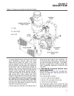
The thermal valve has two entrance ports and two
exit ports. The entrance ports will be referred to as
Port A and Port B. Port A accepts fluid from the
sump and Port B accepts fluid from the cooler. The
exit ports will be referred to as Port C and Port D.
Port C routes fluid to the cooler and Port D routes
fluid to the compressor.
As previously stated, upon start-up, the fluid tem-
perature is cool, and routing to the cooler is not
required. The fluid first enters the thermal valve
through Port A and then flows on to the compressor
unit through Port D, bypassing the cooler. As the
compressor continues to operate, the temperature
of the fluid rises and the thermal valve element
begins to shift. This forces a portion of the fluid to
the fluid cooler through Port C. The cooler is a radi-
ator-type that works in conjunction with the engine
fan. The fan draws air through the cooler removing
the heat of compression from the fluid. From the
cooler, the fluid is routed back to the thermal valve,
entering at Port B. Before the temperature of the
fluid becomes high enough that Port A is complete-
ly shifted, cooled fluid entering at Port B is mixed
with warmer fluid entering at Port A. When the tem-
perature of the fluid entering at Port A reaches
210°F (99°C), the thermal element shifts complete-
Summary of Contents for 1350XH
Page 6: ......
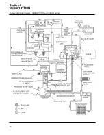
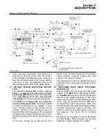
Page 18: ...Section 2 DESCRIPTION 12 Figure 2 3A Control System 900XH 1150XH and 1350XH Models...
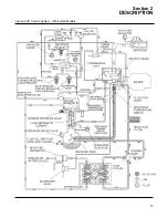
Page 19: ...Section 2 DESCRIPTION 13 Figure 2 3B Control System Aftercooled Models...
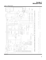
Page 29: ...Section 2 DESCRIPTION 23 Figure 2 7 Wiring Diagram 02250145 161R01...
Page 30: ...NOTES 24...
Page 33: ...Section 3 SPECIFICATIONS 27 02250135 977R03 Figure 3 2 Identification Compressor Assembly...
Page 34: ...NOTES 28...
Page 38: ...NOTES 32...
Page 54: ...Section 7 ILLUSTRATIONS AND PARTS 48 02250127 622R08 7 3 ENGINE AND COMPRESSOR MOUNTING...
Page 56: ...Section 7 ILLUSTRATIONS AND PARTS 50 02250127 622R08 7 3 ENGINE AND COMPRESSOR MOUNTING...
Page 58: ...Section 7 ILLUSTRATIONS AND PARTS 52 02250136 060R02 7 4 AIR INLET SYSTEM ALL MODELS...
Page 60: ...Section 7 ILLUSTRATIONS AND PARTS 54 02250136 060R02 7 4 AIR INLET SYSTEM ALL MODELS...
Page 62: ...Section 7 ILLUSTRATIONS AND PARTS 56 02250136 062R02 7 5 EXHAUST SYSTEM ALL MODELS...
Page 72: ...Section 7 ILLUSTRATIONS AND PARTS 66 02250127 633R02 7 7 ENGINE RADIATOR ASSEMBLY ALL MODELS...
Page 74: ...Section 7 ILLUSTRATIONS AND PARTS 68 7 8 AFTERCOOLER MOUNTING ALL MODELS 02250150 135R03...
Page 82: ...Section 7 ILLUSTRATIONS AND PARTS 76 02250140 983R01 7 12A INLET VALVE AND PARTS 6 5 900XH...
Page 86: ...Section 7 ILLUSTRATIONS AND PARTS 80 02250054 762R06 7 13A INLET VALVE PARTS 6 5 900XH...
Page 90: ...Section 7 ILLUSTRATIONS AND PARTS 84 02250127 667R10 7 14A DISCHARGE SYSTEM 900XH AND 1150XH...
Page 96: ...Section 7 ILLUSTRATIONS AND PARTS 90 02250148 288R01 7 14C DISCHARGE SYSTEM 1350XH AFTERCOOLED...
Page 98: ...Section 7 ILLUSTRATIONS AND PARTS 92 02250148 288R01 7 14C DISCHARGE SYSTEM 1350XH AFTERCOOLED...
Page 116: ...Section 7 ILLUSTRATIONS AND PARTS 110 02250164 870R01 7 19 MINIMUM PRESSURE CHECK VALVE...
Page 118: ...Section 7 ILLUSTRATIONS AND PARTS 112 02250136 066R00 7 20 FUEL SYSTEM AND PARTS ALL MODELS...
Page 120: ...Section 7 ILLUSTRATIONS AND PARTS 114 02250127 727R01 7 21 ELECTRICAL PARTS ALL MODELS...
Page 126: ...Section 7 ILLUSTRATIONS AND PARTS 120 02250136 503R02 7 23 FRAME AND PARTS...
Page 128: ...Section 7 ILLUSTRATIONS AND PARTS 122 7 24 DECAL GROUP...
Page 130: ...Section 7 ILLUSTRATIONS AND PARTS 124 7 24 DECAL GROUP...
Page 132: ...Section 7 ILLUSTRATIONS AND PARTS 126 7 24 DECAL GROUP...
Page 134: ...Section 7 ILLUSTRATIONS AND PARTS 128 7 24 DECAL GROUP...
Page 136: ...Section 7 ILLUSTRATIONS AND PARTS 130 7 25 DECAL LOCATIONS 02250136 067R03...
Page 138: ...Section 7 ILLUSTRATIONS AND PARTS 132 7 25 DECAL LOCATIONS 02250136 067R03...
Page 140: ...NOTES 134...
Page 141: ......


