to the inlet valve causing the check spring in the
inlet valve to close the air inlet valve. This sends a
pressure signal to the blowdown valve causing it to
open and vent the pressure in the system. After the
pressure is vented, the blowdown valve spring
returns the blowdown valve to the closed position.
2.7 AIR INLET SYSTEM, FUNCTIONAL DESCRIP-
TION
The compressor
inlet system
consists of
two air
filters
, a c
ompressor air inlet valve
and
inter-
connecting piping
to the engine and compressor.
Also,
nylon tubing
from air filter
restriction indi-
cator gauges
on instrument panel are provided.
The
air filters
are
2-stage units
with a
safety ele-
ment dry element-type filter
. This filter is capable
of cleaning extremely dirty air. However, in such
cases, frequent checks of the air filter will be
required. Referring to the instrument panel, the
engine air filter restriction gauge or the compressor
air filter restriction gauge will indicate when restric-
tion of the air passing through the filter becomes too
high.
At this time, change the air filter element. See
Section 5 for Air Filter Maintenance Procedures.
These indicators should be checked daily, after
start-up under normal conditions.
The compressor air inlet valve controls the amount
of air intake of the compressor in response to the air
demand.
2.8 INSTRUMENT PANEL GROUP, FUNCTIONAL
DESCRIPTION
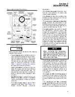
. The instrument panel group
consists of an
EMS
(
E
ngine
M
onitoring
S
ystem).
On the
EMS unit
there are ten warning lamps avail-
able for system related diagnostics. These diag-
nostics can be used for system performance moni-
toring. They are located on the main EMS unit in
two rows of five: coolant temperature, intake mani-
fold temperature, fuel temperature, battery voltage,
accessory temperature, engine oil pressure, fuel
pressure, coolant level, engine derate, and acces-
sory pressure. See Figure
for functional
lamps.
Beneath the warning lamps is a digital LCD display
to scroll through different engine and machine
parameters. Digital readouts are as follows:
Section 2
DESCRIPTION
15
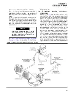
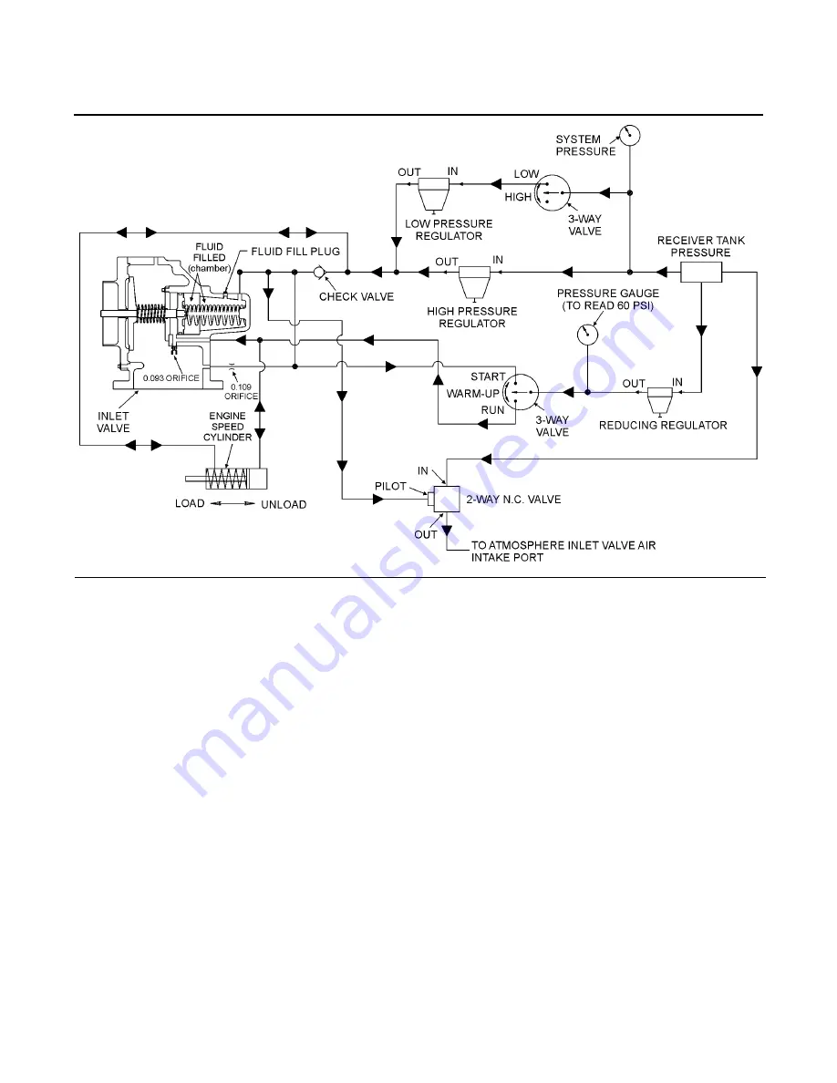
Figure 2-4 Control System Diagram
02250077-331R03
Summary of Contents for 1350XH
Page 6: ......
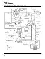
Page 18: ...Section 2 DESCRIPTION 12 Figure 2 3A Control System 900XH 1150XH and 1350XH Models...
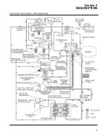
Page 19: ...Section 2 DESCRIPTION 13 Figure 2 3B Control System Aftercooled Models...
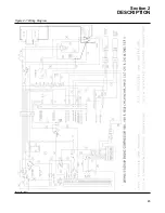
Page 29: ...Section 2 DESCRIPTION 23 Figure 2 7 Wiring Diagram 02250145 161R01...
Page 30: ...NOTES 24...
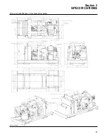
Page 33: ...Section 3 SPECIFICATIONS 27 02250135 977R03 Figure 3 2 Identification Compressor Assembly...
Page 34: ...NOTES 28...
Page 38: ...NOTES 32...
Page 54: ...Section 7 ILLUSTRATIONS AND PARTS 48 02250127 622R08 7 3 ENGINE AND COMPRESSOR MOUNTING...
Page 56: ...Section 7 ILLUSTRATIONS AND PARTS 50 02250127 622R08 7 3 ENGINE AND COMPRESSOR MOUNTING...
Page 58: ...Section 7 ILLUSTRATIONS AND PARTS 52 02250136 060R02 7 4 AIR INLET SYSTEM ALL MODELS...
Page 60: ...Section 7 ILLUSTRATIONS AND PARTS 54 02250136 060R02 7 4 AIR INLET SYSTEM ALL MODELS...
Page 62: ...Section 7 ILLUSTRATIONS AND PARTS 56 02250136 062R02 7 5 EXHAUST SYSTEM ALL MODELS...
Page 72: ...Section 7 ILLUSTRATIONS AND PARTS 66 02250127 633R02 7 7 ENGINE RADIATOR ASSEMBLY ALL MODELS...
Page 74: ...Section 7 ILLUSTRATIONS AND PARTS 68 7 8 AFTERCOOLER MOUNTING ALL MODELS 02250150 135R03...
Page 82: ...Section 7 ILLUSTRATIONS AND PARTS 76 02250140 983R01 7 12A INLET VALVE AND PARTS 6 5 900XH...
Page 86: ...Section 7 ILLUSTRATIONS AND PARTS 80 02250054 762R06 7 13A INLET VALVE PARTS 6 5 900XH...
Page 90: ...Section 7 ILLUSTRATIONS AND PARTS 84 02250127 667R10 7 14A DISCHARGE SYSTEM 900XH AND 1150XH...
Page 96: ...Section 7 ILLUSTRATIONS AND PARTS 90 02250148 288R01 7 14C DISCHARGE SYSTEM 1350XH AFTERCOOLED...
Page 98: ...Section 7 ILLUSTRATIONS AND PARTS 92 02250148 288R01 7 14C DISCHARGE SYSTEM 1350XH AFTERCOOLED...
Page 116: ...Section 7 ILLUSTRATIONS AND PARTS 110 02250164 870R01 7 19 MINIMUM PRESSURE CHECK VALVE...
Page 118: ...Section 7 ILLUSTRATIONS AND PARTS 112 02250136 066R00 7 20 FUEL SYSTEM AND PARTS ALL MODELS...
Page 120: ...Section 7 ILLUSTRATIONS AND PARTS 114 02250127 727R01 7 21 ELECTRICAL PARTS ALL MODELS...
Page 126: ...Section 7 ILLUSTRATIONS AND PARTS 120 02250136 503R02 7 23 FRAME AND PARTS...
Page 128: ...Section 7 ILLUSTRATIONS AND PARTS 122 7 24 DECAL GROUP...
Page 130: ...Section 7 ILLUSTRATIONS AND PARTS 124 7 24 DECAL GROUP...
Page 132: ...Section 7 ILLUSTRATIONS AND PARTS 126 7 24 DECAL GROUP...
Page 134: ...Section 7 ILLUSTRATIONS AND PARTS 128 7 24 DECAL GROUP...
Page 136: ...Section 7 ILLUSTRATIONS AND PARTS 130 7 25 DECAL LOCATIONS 02250136 067R03...
Page 138: ...Section 7 ILLUSTRATIONS AND PARTS 132 7 25 DECAL LOCATIONS 02250136 067R03...
Page 140: ...NOTES 134...
Page 141: ......

