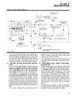
ice the air filter.
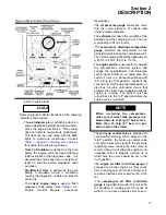
• The
sump tank separator element restric-
tion gauge
is provided to monitor sump
tank separator element restriction. A reading
over 10 psid (0.7 bar) or in red zone, indi-
cates time to service the element.
• The
scroll switch
toggled to the left will indi-
cate gauges pertaining to the engine.
Toggled to the right will convert reading from
Metric to English.
• Check engine and warning lamp for further
engine diagnostics. See Section 2.9 and
Table 2, Possible Performance Effect of
Active Diagnostic Codes.
• The
compressor discharge high tempera-
ture light
or the l
ow fuel level light
will
remain on, indicating the specific problem,
until the rotary switch (engine switch) is
turned to "OFF" position. When the starter
switch is initially turned on, the lights will
come on to check bulb function. The lights
should go out after 15 seconds.
• The
low fuel lamp
indicates a low fuel shut-
down or open circuit.
• The
compressor high temperature lamp
indicates a receiver or discharge high tem-
perature shutdown. Could also indicate an
open circuit.
•
HI/LO selector valve
; HI position allows
machine to operate at rated pressure (350
psig [24.1 bar]). The LO position forces
machine to run at ( 175 psig [ 12.1 bar])
rated speed.
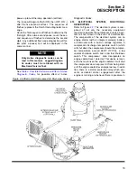
2.9 ENGINE CONTROL MODULE, FUNCTIONAL
DESCRIPTION
Diagnostic Fault Codes are provided to indicate an
electrical or electronic problem has been detected
by the ECM (Engine Control Module). In some
cases the engine performance can be affected
when the condition causing the code exists. More
frequently, however, the operator cannot detect any
difference in the engine performance.
If the operator indicates a performance problem
occurs whenever the Check Engine Lamp is flash-
ing, the diagnostic code may indicate the cause of
the problem, and should be corrected.
If the operator does not indicate a problem with the
engine performance and a diagnostic code is
logged by the ECM, it indicates the ECM detected
an abnormal condition, but it did not affect perform-
ance.
If this is the case, unless there are several occur-
rences of the code in a very short period of time, or,
the ECM is indicating an Active Code at the present
time, there is most likely nothing wrong with the sys-
tem.
The diagnostic FLASH CODE may be retrieved
using this lamp.
The lamp is not required for engine operation, how-
ever it can be useful to determine Active diagnostic
codes. The lamp will illuminate (ON) at initial ECM
Section 2
DESCRIPTION
18
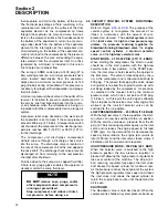
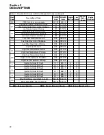
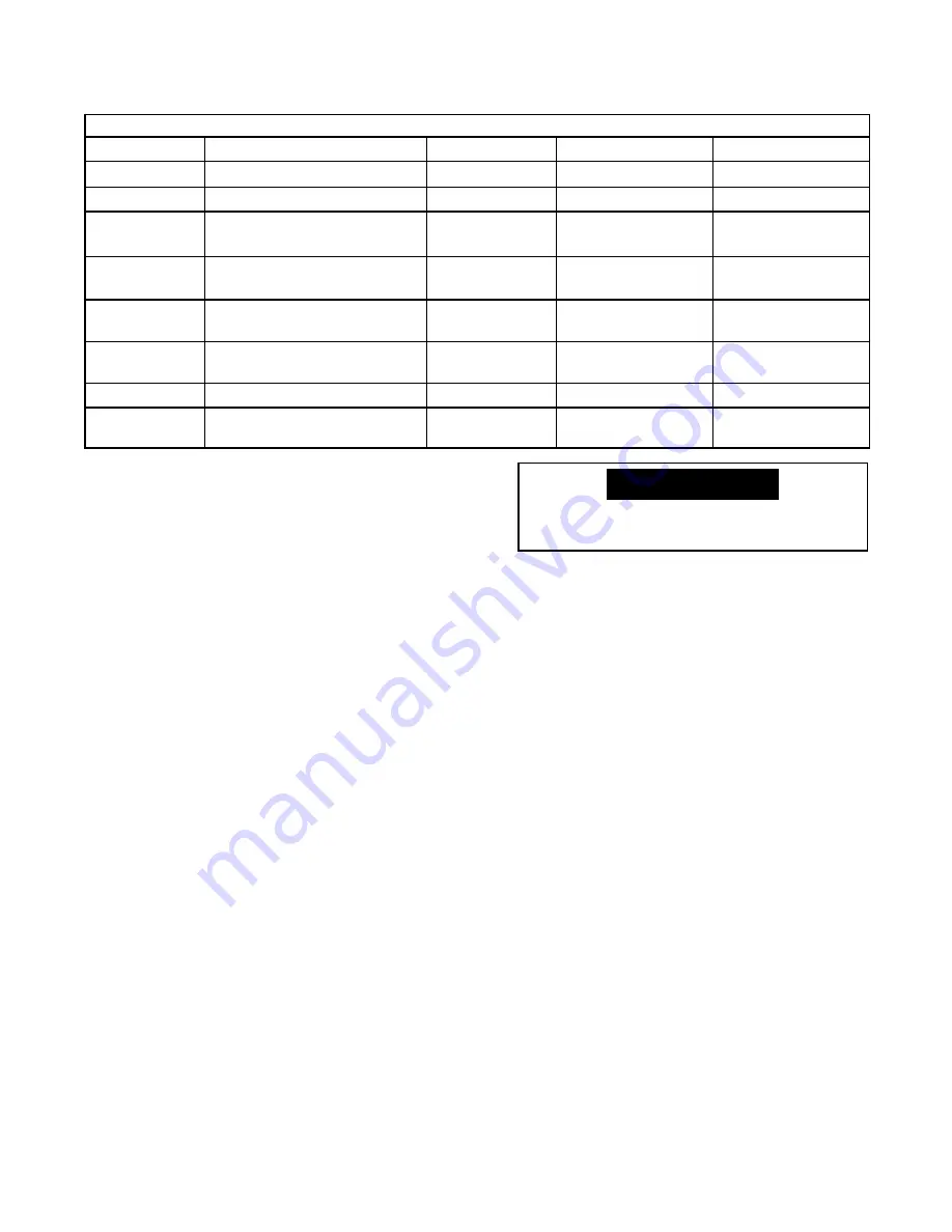
Table 1 - Engine to Warning Lamp Actions
CID-FMI
Description
Warning Lamp
Time to Shutdown
Start/Restart Time
100 - 01
Low Fluid Pressure Warning
ON
No
No
100 - 11
Very Low Fluid Pressure
Flashing
30 Seconds
18 Seconds
105 - 00
High Inlet Manifold Air
Temperature Warning
ON
No
No
105 - 11
Very High Inlet Manifold Air
Temperature
ON
No
No
110 - 00
High Coolant Temperature
Warning
Flashing
No
No
110 - 11
Very High Coolant
Temperature
Flashing
20 Seconds
60 Seconds
111 - 01
Low Coolant Level Warning
On
No
No
111 - 11
Very Low Coolant Level
Warning
Flashing
30 Seconds
80 Seconds
An open in any safety circuit will not
allow machine to start.
NOTE
Summary of Contents for 1350XH
Page 6: ......
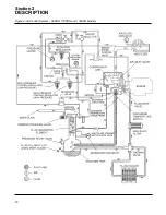
Page 18: ...Section 2 DESCRIPTION 12 Figure 2 3A Control System 900XH 1150XH and 1350XH Models...
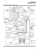
Page 19: ...Section 2 DESCRIPTION 13 Figure 2 3B Control System Aftercooled Models...
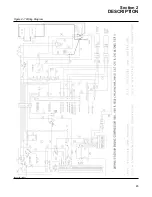
Page 29: ...Section 2 DESCRIPTION 23 Figure 2 7 Wiring Diagram 02250145 161R01...
Page 30: ...NOTES 24...
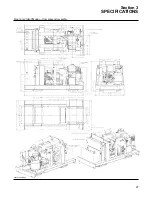
Page 33: ...Section 3 SPECIFICATIONS 27 02250135 977R03 Figure 3 2 Identification Compressor Assembly...
Page 34: ...NOTES 28...
Page 38: ...NOTES 32...
Page 54: ...Section 7 ILLUSTRATIONS AND PARTS 48 02250127 622R08 7 3 ENGINE AND COMPRESSOR MOUNTING...
Page 56: ...Section 7 ILLUSTRATIONS AND PARTS 50 02250127 622R08 7 3 ENGINE AND COMPRESSOR MOUNTING...
Page 58: ...Section 7 ILLUSTRATIONS AND PARTS 52 02250136 060R02 7 4 AIR INLET SYSTEM ALL MODELS...
Page 60: ...Section 7 ILLUSTRATIONS AND PARTS 54 02250136 060R02 7 4 AIR INLET SYSTEM ALL MODELS...
Page 62: ...Section 7 ILLUSTRATIONS AND PARTS 56 02250136 062R02 7 5 EXHAUST SYSTEM ALL MODELS...
Page 72: ...Section 7 ILLUSTRATIONS AND PARTS 66 02250127 633R02 7 7 ENGINE RADIATOR ASSEMBLY ALL MODELS...
Page 74: ...Section 7 ILLUSTRATIONS AND PARTS 68 7 8 AFTERCOOLER MOUNTING ALL MODELS 02250150 135R03...
Page 82: ...Section 7 ILLUSTRATIONS AND PARTS 76 02250140 983R01 7 12A INLET VALVE AND PARTS 6 5 900XH...
Page 86: ...Section 7 ILLUSTRATIONS AND PARTS 80 02250054 762R06 7 13A INLET VALVE PARTS 6 5 900XH...
Page 90: ...Section 7 ILLUSTRATIONS AND PARTS 84 02250127 667R10 7 14A DISCHARGE SYSTEM 900XH AND 1150XH...
Page 96: ...Section 7 ILLUSTRATIONS AND PARTS 90 02250148 288R01 7 14C DISCHARGE SYSTEM 1350XH AFTERCOOLED...
Page 98: ...Section 7 ILLUSTRATIONS AND PARTS 92 02250148 288R01 7 14C DISCHARGE SYSTEM 1350XH AFTERCOOLED...
Page 116: ...Section 7 ILLUSTRATIONS AND PARTS 110 02250164 870R01 7 19 MINIMUM PRESSURE CHECK VALVE...
Page 118: ...Section 7 ILLUSTRATIONS AND PARTS 112 02250136 066R00 7 20 FUEL SYSTEM AND PARTS ALL MODELS...
Page 120: ...Section 7 ILLUSTRATIONS AND PARTS 114 02250127 727R01 7 21 ELECTRICAL PARTS ALL MODELS...
Page 126: ...Section 7 ILLUSTRATIONS AND PARTS 120 02250136 503R02 7 23 FRAME AND PARTS...
Page 128: ...Section 7 ILLUSTRATIONS AND PARTS 122 7 24 DECAL GROUP...
Page 130: ...Section 7 ILLUSTRATIONS AND PARTS 124 7 24 DECAL GROUP...
Page 132: ...Section 7 ILLUSTRATIONS AND PARTS 126 7 24 DECAL GROUP...
Page 134: ...Section 7 ILLUSTRATIONS AND PARTS 128 7 24 DECAL GROUP...
Page 136: ...Section 7 ILLUSTRATIONS AND PARTS 130 7 25 DECAL LOCATIONS 02250136 067R03...
Page 138: ...Section 7 ILLUSTRATIONS AND PARTS 132 7 25 DECAL LOCATIONS 02250136 067R03...
Page 140: ...NOTES 134...
Page 141: ......

