Section 5
MAINTENANCE
33
5.1 GENERAL
A good maintenance program is the key to long
compressor life. Below is a program that when
adhered to, should keep the compressor in top
operating condition. For engine maintenance
requirements, refer to the Engine Operator's
Manual for a detailed description of service instruc-
tions. See Parts Replacement and Adjustment
Procedures for a detailed description of specific
compressor system components. Prior to perform-
ing maintenance, read the CIMA Safety Manual, if
applicable.
Stop compressor and relieve all internal pressure
before doing so.
5.2 DAILY OPERATION
Prior to starting the compressor, it is necessary to
check the fluid level in the sump. Should the level
be low, simply add the necessary amount. If the
addition of fluid becomes too frequent, a simple
problem has developed which is causing this
excessive loss. See the Troubleshooting Section
(5.11) under Excessive Fluid Consumption for a
probable cause and remedy. Also check the engine
oil level and the radiator coolant level prior to start-
ing.
After a routine start has been made, observe the
instrument panel gauges and be sure they monitor
the correct readings for their particular phase of
operation. After the compressor has warmed up, it
is recommended that a general check on the over-
all compressor and instrument panel be made to
assure that the compressor is running properly.
Also check the air filter restriction gauges. Should
they indicate restriction, replace the elements
immediately (see Air Filter Maintenance in Section
5.10).
5.3 MAINTENANCE AFTER INITIAL 50 HOURS OF
OPERATION
After the initial 50 hours of operation, a few simple
maintenance routines can rid the system of any
possible foreign materials, if any. Perform the fol-
lowing maintenance operations to prevent unnec-
essary problems.
1. Clean the return line orifice and strainer.
2. Change compressor fluid filter.
3. Check Engine Operator's Manual for required
service.
5.4 MAINTENANCE EVERY 100 HOURS
After 100 hours of operation, it will be necessary to
perform the following:
1. Check the battery level and fill with water if nec-
essary.
5.5 MAINTENANCE EVERY 250 HOURS
Perform the following after every 250 hours of oper-
ation:
1. Check fan belt tension.
2. Clean the radiator and cooler exterior. Depending
on how contaminated the atmosphere may be,
more frequent cooler and radiator cleaning may
be necessary. To clean between fluid cooler and
radiator, the three (3) bolts securing the top of
the fluid cooler to the top mounting bracket
should be removed, allowing the fluid cooler to
swing down on its lower hinge. This will allow
easier access to clean between the fluid cooler
and radiator cores.
3. Check Engine Operator's Manual for required
service.
4. Change the engine oil and oil filter. This is best
done when the engine is hot.
5.6 MAINTENANCE EVERY 300 HOURS
When using fluids other than Sullair AWF, change
the compressor fluid and replace the fluid filter ele-
ment (See maintenance procedure in Section 5.10).
5.7 MAINTENANCE EVERY 500 HOURS
When using Sullair AWF, replace the fluid filter ele-
ment and change compressor fluid. (See mainte-
nance procedures in Section 5.10).
5.8 MAINTENANCE EVERY 1000 HOURS
Perform the following after every 1000 hours of
operation:
DO NOT
remove caps, plugs and/or
other components when compressor is
running or pressurized.
Stop compressor and relieve all inter-
nal pressure before doing so.
WARNING
The radiator and engine cooling sys-
tem must be drained and flushed every
two (2) years. Replace the coolant with
a solution of 50% ethylene glycol and
50% water or as required for your geo-
graphic location.
DO NOT
use a leak
sealing type of anti-freeze. Should a
100% water solution be used, a non-
chromate rust inhibitor must be added.
NOTE
Summary of Contents for 1350XH
Page 6: ......
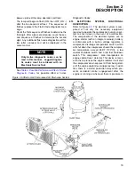
Page 18: ...Section 2 DESCRIPTION 12 Figure 2 3A Control System 900XH 1150XH and 1350XH Models...
Page 19: ...Section 2 DESCRIPTION 13 Figure 2 3B Control System Aftercooled Models...
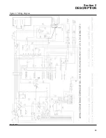
Page 29: ...Section 2 DESCRIPTION 23 Figure 2 7 Wiring Diagram 02250145 161R01...
Page 30: ...NOTES 24...
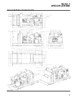
Page 33: ...Section 3 SPECIFICATIONS 27 02250135 977R03 Figure 3 2 Identification Compressor Assembly...
Page 34: ...NOTES 28...
Page 38: ...NOTES 32...
Page 54: ...Section 7 ILLUSTRATIONS AND PARTS 48 02250127 622R08 7 3 ENGINE AND COMPRESSOR MOUNTING...
Page 56: ...Section 7 ILLUSTRATIONS AND PARTS 50 02250127 622R08 7 3 ENGINE AND COMPRESSOR MOUNTING...
Page 58: ...Section 7 ILLUSTRATIONS AND PARTS 52 02250136 060R02 7 4 AIR INLET SYSTEM ALL MODELS...
Page 60: ...Section 7 ILLUSTRATIONS AND PARTS 54 02250136 060R02 7 4 AIR INLET SYSTEM ALL MODELS...
Page 62: ...Section 7 ILLUSTRATIONS AND PARTS 56 02250136 062R02 7 5 EXHAUST SYSTEM ALL MODELS...
Page 72: ...Section 7 ILLUSTRATIONS AND PARTS 66 02250127 633R02 7 7 ENGINE RADIATOR ASSEMBLY ALL MODELS...
Page 74: ...Section 7 ILLUSTRATIONS AND PARTS 68 7 8 AFTERCOOLER MOUNTING ALL MODELS 02250150 135R03...
Page 82: ...Section 7 ILLUSTRATIONS AND PARTS 76 02250140 983R01 7 12A INLET VALVE AND PARTS 6 5 900XH...
Page 86: ...Section 7 ILLUSTRATIONS AND PARTS 80 02250054 762R06 7 13A INLET VALVE PARTS 6 5 900XH...
Page 90: ...Section 7 ILLUSTRATIONS AND PARTS 84 02250127 667R10 7 14A DISCHARGE SYSTEM 900XH AND 1150XH...
Page 96: ...Section 7 ILLUSTRATIONS AND PARTS 90 02250148 288R01 7 14C DISCHARGE SYSTEM 1350XH AFTERCOOLED...
Page 98: ...Section 7 ILLUSTRATIONS AND PARTS 92 02250148 288R01 7 14C DISCHARGE SYSTEM 1350XH AFTERCOOLED...
Page 116: ...Section 7 ILLUSTRATIONS AND PARTS 110 02250164 870R01 7 19 MINIMUM PRESSURE CHECK VALVE...
Page 118: ...Section 7 ILLUSTRATIONS AND PARTS 112 02250136 066R00 7 20 FUEL SYSTEM AND PARTS ALL MODELS...
Page 120: ...Section 7 ILLUSTRATIONS AND PARTS 114 02250127 727R01 7 21 ELECTRICAL PARTS ALL MODELS...
Page 126: ...Section 7 ILLUSTRATIONS AND PARTS 120 02250136 503R02 7 23 FRAME AND PARTS...
Page 128: ...Section 7 ILLUSTRATIONS AND PARTS 122 7 24 DECAL GROUP...
Page 130: ...Section 7 ILLUSTRATIONS AND PARTS 124 7 24 DECAL GROUP...
Page 132: ...Section 7 ILLUSTRATIONS AND PARTS 126 7 24 DECAL GROUP...
Page 134: ...Section 7 ILLUSTRATIONS AND PARTS 128 7 24 DECAL GROUP...
Page 136: ...Section 7 ILLUSTRATIONS AND PARTS 130 7 25 DECAL LOCATIONS 02250136 067R03...
Page 138: ...Section 7 ILLUSTRATIONS AND PARTS 132 7 25 DECAL LOCATIONS 02250136 067R03...
Page 140: ...NOTES 134...
Page 141: ......

