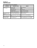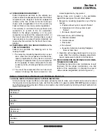
1. Clean the return line orifice and strainer.
5.9 PARTS REPLACEMENT AND ADJUSTMENT
PROCEDURES
COMPRESSOR FLUID CHANGE PROCEDURE
Warm-up the compressor for 5 to 10 minutes to
warm the fluid. Shut the compressor off and relieve
all internal pressure before proceeding. Drain the
fluid sump by removing the plug at the bottom of the
sump tank. Change the compressor fluid and
replace the fluid filter element. For element replace-
ment see procedure for servicing the fluid filter in
this section. Fill the sump with fluid according to
specifications in
.
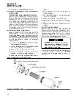
SERVICING THE MAIN FLUID FILTER
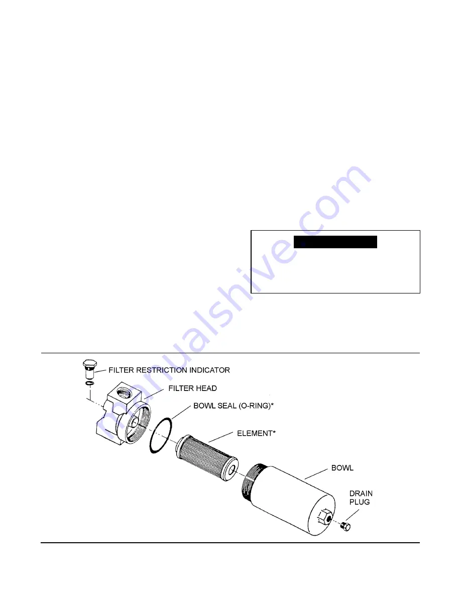
Refer to Figure
5-1
. The main fluid filter (P/N
02250111-592) is located schematically in the
coolant line between the receiver/sump and the
compressor unit. The main filter element is replace-
able. For installation of the filter element and o-ring
kit (P/N 250031-850), follow the procedure
explained below.
1. The compressor
MUST
be shut off and system
pressure
MUST
be relieved.
2. Drain by removing drain plug at bottom of bowl
and catching drainage in a container.
3. Rotate bowl counterclockwise and remove.
4. Remove element and o-ring from housing and
discard. This element is
NOT
cleanable.
5. Make sure mounting surface of filter head is
clean.
6. Apply a light film of fluid to o-ring and place it in
its proper position.
7. Place new, clean element in housing, centering it
on location in the head.
8. Inspect bowl seal and replace if necessary.
9. Replace bowl. Rotate clockwise and hand-tight-
en.
10. Replace drain plug. Torque to 15-20 ft.-lbs. (20-
27 Nm).
AIR FILTER MAINTENANCE
. Air filter (P/N 02250049-036
[engine]) (P/N 02250053-402 [compressor]) main-
tenance should be performed when indicated on
instrument panel by the engine air filter restriction
gauge. The air filters are both equipped with a pri-
mary element and secondary element each.
The secondary element must be replaced after
every third primary element change.
DO NOT
reconnect the secondary element once it is
removed.
Section 5
MAINTENANCE
34
Figure 5-1 Main Filter (P/N 02250111-592)
DO NOT
strike elements against any
hard surface to dislodge dust. This will
damage the sealing surfaces and pos-
sibly rupture the elements.
NOTE
*Repair Kit P/N 250031-850
Summary of Contents for 1350XH
Page 6: ......
Page 18: ...Section 2 DESCRIPTION 12 Figure 2 3A Control System 900XH 1150XH and 1350XH Models...
Page 19: ...Section 2 DESCRIPTION 13 Figure 2 3B Control System Aftercooled Models...
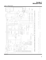
Page 29: ...Section 2 DESCRIPTION 23 Figure 2 7 Wiring Diagram 02250145 161R01...
Page 30: ...NOTES 24...
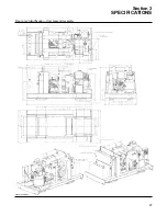
Page 33: ...Section 3 SPECIFICATIONS 27 02250135 977R03 Figure 3 2 Identification Compressor Assembly...
Page 34: ...NOTES 28...
Page 38: ...NOTES 32...
Page 54: ...Section 7 ILLUSTRATIONS AND PARTS 48 02250127 622R08 7 3 ENGINE AND COMPRESSOR MOUNTING...
Page 56: ...Section 7 ILLUSTRATIONS AND PARTS 50 02250127 622R08 7 3 ENGINE AND COMPRESSOR MOUNTING...
Page 58: ...Section 7 ILLUSTRATIONS AND PARTS 52 02250136 060R02 7 4 AIR INLET SYSTEM ALL MODELS...
Page 60: ...Section 7 ILLUSTRATIONS AND PARTS 54 02250136 060R02 7 4 AIR INLET SYSTEM ALL MODELS...
Page 62: ...Section 7 ILLUSTRATIONS AND PARTS 56 02250136 062R02 7 5 EXHAUST SYSTEM ALL MODELS...
Page 72: ...Section 7 ILLUSTRATIONS AND PARTS 66 02250127 633R02 7 7 ENGINE RADIATOR ASSEMBLY ALL MODELS...
Page 74: ...Section 7 ILLUSTRATIONS AND PARTS 68 7 8 AFTERCOOLER MOUNTING ALL MODELS 02250150 135R03...
Page 82: ...Section 7 ILLUSTRATIONS AND PARTS 76 02250140 983R01 7 12A INLET VALVE AND PARTS 6 5 900XH...
Page 86: ...Section 7 ILLUSTRATIONS AND PARTS 80 02250054 762R06 7 13A INLET VALVE PARTS 6 5 900XH...
Page 90: ...Section 7 ILLUSTRATIONS AND PARTS 84 02250127 667R10 7 14A DISCHARGE SYSTEM 900XH AND 1150XH...
Page 96: ...Section 7 ILLUSTRATIONS AND PARTS 90 02250148 288R01 7 14C DISCHARGE SYSTEM 1350XH AFTERCOOLED...
Page 98: ...Section 7 ILLUSTRATIONS AND PARTS 92 02250148 288R01 7 14C DISCHARGE SYSTEM 1350XH AFTERCOOLED...
Page 116: ...Section 7 ILLUSTRATIONS AND PARTS 110 02250164 870R01 7 19 MINIMUM PRESSURE CHECK VALVE...
Page 118: ...Section 7 ILLUSTRATIONS AND PARTS 112 02250136 066R00 7 20 FUEL SYSTEM AND PARTS ALL MODELS...
Page 120: ...Section 7 ILLUSTRATIONS AND PARTS 114 02250127 727R01 7 21 ELECTRICAL PARTS ALL MODELS...
Page 126: ...Section 7 ILLUSTRATIONS AND PARTS 120 02250136 503R02 7 23 FRAME AND PARTS...
Page 128: ...Section 7 ILLUSTRATIONS AND PARTS 122 7 24 DECAL GROUP...
Page 130: ...Section 7 ILLUSTRATIONS AND PARTS 124 7 24 DECAL GROUP...
Page 132: ...Section 7 ILLUSTRATIONS AND PARTS 126 7 24 DECAL GROUP...
Page 134: ...Section 7 ILLUSTRATIONS AND PARTS 128 7 24 DECAL GROUP...
Page 136: ...Section 7 ILLUSTRATIONS AND PARTS 130 7 25 DECAL LOCATIONS 02250136 067R03...
Page 138: ...Section 7 ILLUSTRATIONS AND PARTS 132 7 25 DECAL LOCATIONS 02250136 067R03...
Page 140: ...NOTES 134...
Page 141: ......

