Section 5
MAINTENANCE
38
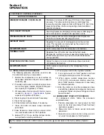
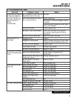
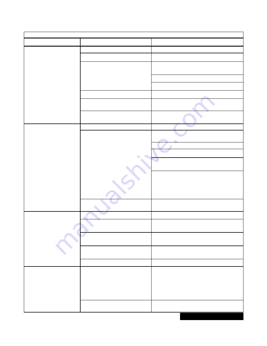
5.11 TROUBLESHOOTING GUIDE
SYMPTOM
PROBABLE CAUSE
REMEDY
COMPRESSOR WILL NOT
START
No Fuel
Check fuel level and add fuel if necessary.
Plugged Fuel Filter
Replace the element.
Low Battery Voltage
Check electrolyte level and add distilled water
and recharge if necessary.
Loose battery cables; tighten cables.
Dirty battery cables; clean thoroughly.
Plugged Air Filter
Replace the element.
Engine Problems May Have
Developed
Refer to Engine Operator’s Manual.
Tripped Circuit Breaker on
Instrument Panel
Check and reset if necessary.
COMPRESSOR SHUTS
DOWNWITH AIR DEMAND
PRESENT
No Fuel
Check fuel gauge and add fuel if necessary.
Compressor Discharge
Temperature Switch is Open
Cooling air flow is insufficient; clean cooler
and check for proper ventilation.
Low fluid sump level; add fluid.
Dirty compressor fluid filter; change element.
Thermostatic element is not functioning prop-
erly; change the thermostatic element.
Defective discharge temperature switch;
check for a short or open circuit to the engine
fuel solenoid. Should this check out normal, it
could be possible that the temperature switch
itself is defective.
Tripped Circuit Breaker on
Instrument Panel
Check and reset if necessary.
COMPRESSOR WILL NOT
BUILD UP FULL DIS-
CHARGE PRESSURE
Air Demand is Too Great
Check service lines for leaks or open valves.
Dirty Air Filter
Check the filter gauges on instrument panel
and change element if required.
Pressure Regulator Out of
Adjustment
Adjust regulator according to control adjust-
ment instructions in the Maintenance section.
Defective Pressure Regulator
Check diaphragm and replace if necessary
(kit available).
Defective Air Inlet Cylinder
Replace cylinder.
IMPROPER UNLOADING
WITH AN EXCESSIVE
PRESSURE BUILD-UP
CAUSING PRESSURE
RELIEF VALVE TO OPEN
Fluid Charge Lost from Spring
Chamber on Inlet Valve
Add fluid to inlet valve spring chamber by
removing plugs (Fig. 5-3) in the top of the
spring chamber and filling with compressor
fluid. Some fluid may leak from the control
regulator at first but will stop leaking when
fluid level in the spring chamber equalizes.
Pressure Regulating Valve is Set
Too High
Readjust.
Continued ...
Summary of Contents for 1350XH
Page 6: ......
Page 18: ...Section 2 DESCRIPTION 12 Figure 2 3A Control System 900XH 1150XH and 1350XH Models...
Page 19: ...Section 2 DESCRIPTION 13 Figure 2 3B Control System Aftercooled Models...
Page 29: ...Section 2 DESCRIPTION 23 Figure 2 7 Wiring Diagram 02250145 161R01...
Page 30: ...NOTES 24...
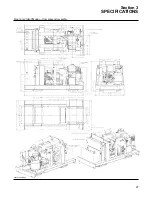
Page 33: ...Section 3 SPECIFICATIONS 27 02250135 977R03 Figure 3 2 Identification Compressor Assembly...
Page 34: ...NOTES 28...
Page 38: ...NOTES 32...
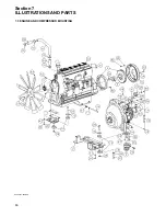
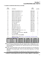
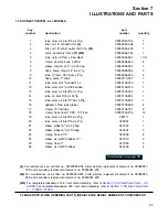
Page 54: ...Section 7 ILLUSTRATIONS AND PARTS 48 02250127 622R08 7 3 ENGINE AND COMPRESSOR MOUNTING...
Page 56: ...Section 7 ILLUSTRATIONS AND PARTS 50 02250127 622R08 7 3 ENGINE AND COMPRESSOR MOUNTING...
Page 58: ...Section 7 ILLUSTRATIONS AND PARTS 52 02250136 060R02 7 4 AIR INLET SYSTEM ALL MODELS...
Page 60: ...Section 7 ILLUSTRATIONS AND PARTS 54 02250136 060R02 7 4 AIR INLET SYSTEM ALL MODELS...
Page 62: ...Section 7 ILLUSTRATIONS AND PARTS 56 02250136 062R02 7 5 EXHAUST SYSTEM ALL MODELS...
Page 72: ...Section 7 ILLUSTRATIONS AND PARTS 66 02250127 633R02 7 7 ENGINE RADIATOR ASSEMBLY ALL MODELS...
Page 74: ...Section 7 ILLUSTRATIONS AND PARTS 68 7 8 AFTERCOOLER MOUNTING ALL MODELS 02250150 135R03...
Page 82: ...Section 7 ILLUSTRATIONS AND PARTS 76 02250140 983R01 7 12A INLET VALVE AND PARTS 6 5 900XH...
Page 86: ...Section 7 ILLUSTRATIONS AND PARTS 80 02250054 762R06 7 13A INLET VALVE PARTS 6 5 900XH...
Page 90: ...Section 7 ILLUSTRATIONS AND PARTS 84 02250127 667R10 7 14A DISCHARGE SYSTEM 900XH AND 1150XH...
Page 96: ...Section 7 ILLUSTRATIONS AND PARTS 90 02250148 288R01 7 14C DISCHARGE SYSTEM 1350XH AFTERCOOLED...
Page 98: ...Section 7 ILLUSTRATIONS AND PARTS 92 02250148 288R01 7 14C DISCHARGE SYSTEM 1350XH AFTERCOOLED...
Page 116: ...Section 7 ILLUSTRATIONS AND PARTS 110 02250164 870R01 7 19 MINIMUM PRESSURE CHECK VALVE...
Page 118: ...Section 7 ILLUSTRATIONS AND PARTS 112 02250136 066R00 7 20 FUEL SYSTEM AND PARTS ALL MODELS...
Page 120: ...Section 7 ILLUSTRATIONS AND PARTS 114 02250127 727R01 7 21 ELECTRICAL PARTS ALL MODELS...
Page 126: ...Section 7 ILLUSTRATIONS AND PARTS 120 02250136 503R02 7 23 FRAME AND PARTS...
Page 128: ...Section 7 ILLUSTRATIONS AND PARTS 122 7 24 DECAL GROUP...
Page 130: ...Section 7 ILLUSTRATIONS AND PARTS 124 7 24 DECAL GROUP...
Page 132: ...Section 7 ILLUSTRATIONS AND PARTS 126 7 24 DECAL GROUP...
Page 134: ...Section 7 ILLUSTRATIONS AND PARTS 128 7 24 DECAL GROUP...
Page 136: ...Section 7 ILLUSTRATIONS AND PARTS 130 7 25 DECAL LOCATIONS 02250136 067R03...
Page 138: ...Section 7 ILLUSTRATIONS AND PARTS 132 7 25 DECAL LOCATIONS 02250136 067R03...
Page 140: ...NOTES 134...
Page 141: ......

