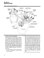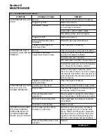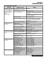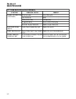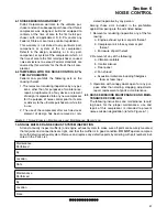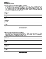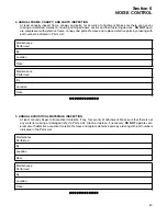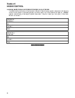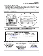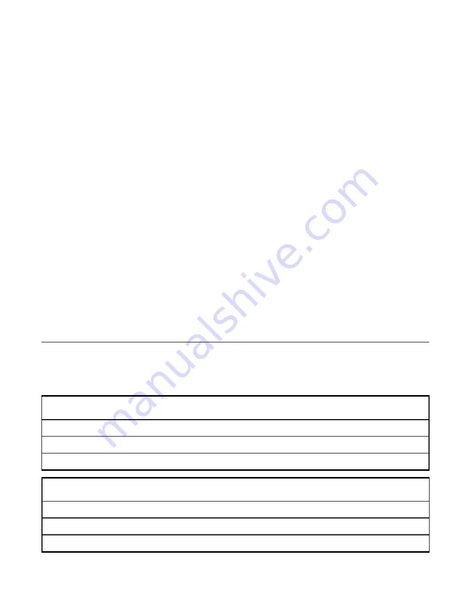
Figure 6-1 Noise Emission Maintenance and Maintenance Record Log
1. ANNUAL MUFFLER AND EXHAUST SYSTEM INSPECTION
At least annually inspect muffler(s) and engine exhaust system to make sure all parts are securely mounted,
that all joints and connections are tight, and that the muffler is in good condition.
DO NOT
operate compres-
sor with defective exhaust system. Remove and replace any defective parts by ordering with part numbers indi-
cated in the Parts List.
Section 6
NOISE CONTROL
41
6.1 NOISE EMISSIONS WARRANTY
Sullair Corporation warrants to the ultimate pur-
chaser and each subsequent purchaser that this air
compressor was designed, built and equipped to
conform at the time of sale to the first retail pur-
chaser, with all applicable U.S. E.P.A. and/or any
Federal, State or Local noise control regulations.
This warranty is not limited to any particular part,
component, or system of the air compressor.
Defects in the design, assembly, or in any part,
component, or system of the compressor which, at
the time of sale to the first retail purchaser, caused
noise emissions to exceed Federal standards are
covered by this warranty for the life of the air com-
pressor.
6.2 TAMPERING WITH THE NOISE CONTROL SYS-
TEM IS PROHIBITED
Federal Law prohibits the following acts or the
causing thereof:
1. The removal or rendering inoperative by any per-
sons, other than for purposes of maintenance,
repair, or replacement, of any device or element
of design incorporated into any new compressor
for the purpose of noise control prior to its sale
or delivery to the ultimate purchaser or while it is
in use.
2. The use of the compressor after such device or
element of design has been removed or ren-
dered inoperative by any person.
Among those acts included in the prohibition
against tampering are the acts listed below:
1. Removal or rendering inoperative any of the fol-
lowing:
a. Engine exhaust system or parts thereof
b. Compressor air intake system or part
thereof
c. Enclosure of part thereof
2. Removal of any of the following:
a. Vibration isolators
b. Control silencer
c. Floor panel
d. Fan shroud
e. Acoustical materials including fiberglass
foam or foam tape
3. Operation with canopy doors open for any pur-
pose other than starting, stopping, adjustment,
repair, replacement of parts or maintenance.
6.3 NOISE EMISSIONS MAINTENANCE AND MAIN-
TENANCE RECORD LOG
The following instructions and maintenance record
log book, for the proper maintenance, use and
repair of this compressor, is intended to prevent
noise emission degradation (refer to Figure 6-1).
Maintenance
Performed
By
Location
Date
Maintenance
Performed
By
Location
Date
•
••
••
••
••
••
••
••
••
••
••
••
•
Summary of Contents for 1350XH
Page 6: ......
Page 18: ...Section 2 DESCRIPTION 12 Figure 2 3A Control System 900XH 1150XH and 1350XH Models...
Page 19: ...Section 2 DESCRIPTION 13 Figure 2 3B Control System Aftercooled Models...
Page 29: ...Section 2 DESCRIPTION 23 Figure 2 7 Wiring Diagram 02250145 161R01...
Page 30: ...NOTES 24...
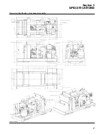
Page 33: ...Section 3 SPECIFICATIONS 27 02250135 977R03 Figure 3 2 Identification Compressor Assembly...
Page 34: ...NOTES 28...
Page 38: ...NOTES 32...
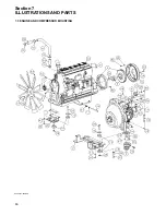
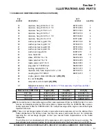
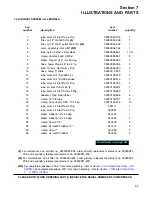
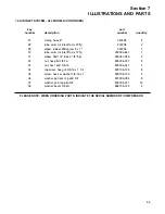
Page 54: ...Section 7 ILLUSTRATIONS AND PARTS 48 02250127 622R08 7 3 ENGINE AND COMPRESSOR MOUNTING...
Page 56: ...Section 7 ILLUSTRATIONS AND PARTS 50 02250127 622R08 7 3 ENGINE AND COMPRESSOR MOUNTING...
Page 58: ...Section 7 ILLUSTRATIONS AND PARTS 52 02250136 060R02 7 4 AIR INLET SYSTEM ALL MODELS...
Page 60: ...Section 7 ILLUSTRATIONS AND PARTS 54 02250136 060R02 7 4 AIR INLET SYSTEM ALL MODELS...
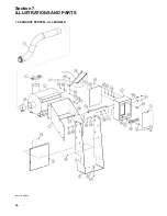
Page 62: ...Section 7 ILLUSTRATIONS AND PARTS 56 02250136 062R02 7 5 EXHAUST SYSTEM ALL MODELS...
Page 72: ...Section 7 ILLUSTRATIONS AND PARTS 66 02250127 633R02 7 7 ENGINE RADIATOR ASSEMBLY ALL MODELS...
Page 74: ...Section 7 ILLUSTRATIONS AND PARTS 68 7 8 AFTERCOOLER MOUNTING ALL MODELS 02250150 135R03...
Page 82: ...Section 7 ILLUSTRATIONS AND PARTS 76 02250140 983R01 7 12A INLET VALVE AND PARTS 6 5 900XH...
Page 86: ...Section 7 ILLUSTRATIONS AND PARTS 80 02250054 762R06 7 13A INLET VALVE PARTS 6 5 900XH...
Page 90: ...Section 7 ILLUSTRATIONS AND PARTS 84 02250127 667R10 7 14A DISCHARGE SYSTEM 900XH AND 1150XH...
Page 96: ...Section 7 ILLUSTRATIONS AND PARTS 90 02250148 288R01 7 14C DISCHARGE SYSTEM 1350XH AFTERCOOLED...
Page 98: ...Section 7 ILLUSTRATIONS AND PARTS 92 02250148 288R01 7 14C DISCHARGE SYSTEM 1350XH AFTERCOOLED...
Page 116: ...Section 7 ILLUSTRATIONS AND PARTS 110 02250164 870R01 7 19 MINIMUM PRESSURE CHECK VALVE...
Page 118: ...Section 7 ILLUSTRATIONS AND PARTS 112 02250136 066R00 7 20 FUEL SYSTEM AND PARTS ALL MODELS...
Page 120: ...Section 7 ILLUSTRATIONS AND PARTS 114 02250127 727R01 7 21 ELECTRICAL PARTS ALL MODELS...
Page 126: ...Section 7 ILLUSTRATIONS AND PARTS 120 02250136 503R02 7 23 FRAME AND PARTS...
Page 128: ...Section 7 ILLUSTRATIONS AND PARTS 122 7 24 DECAL GROUP...
Page 130: ...Section 7 ILLUSTRATIONS AND PARTS 124 7 24 DECAL GROUP...
Page 132: ...Section 7 ILLUSTRATIONS AND PARTS 126 7 24 DECAL GROUP...
Page 134: ...Section 7 ILLUSTRATIONS AND PARTS 128 7 24 DECAL GROUP...
Page 136: ...Section 7 ILLUSTRATIONS AND PARTS 130 7 25 DECAL LOCATIONS 02250136 067R03...
Page 138: ...Section 7 ILLUSTRATIONS AND PARTS 132 7 25 DECAL LOCATIONS 02250136 067R03...
Page 140: ...NOTES 134...
Page 141: ......

