Section 7
ILLUSTRATIONS AND PARTS
51
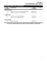
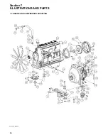
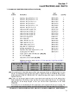
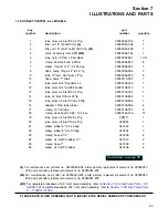
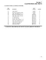
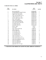
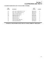
7.3 ENGINE AND COMPRESSOR MOUNTING (CONTINUED)
key
part
number
description
number
quantity
33
capscrew, hex gr8 3/4-10 x 2 1/4
827912-225
1
34
capscrew, hex gr8 3/4-10 x 2 1/2
827912-250
2
35
capscrew, hex gr5 7/16-14 x 3
829107-300
24
36
capscrew, hex gr5 1/2-13 x 1
829108-100
4
37
capscrew, hex gr5 1/2-13 x 3 1/2
829108-350
6
38
capscrew, hex gr5 1-8 x 5 1/2
829116-550
4
39
washer, spr lock reg pltd 7/16
837807-109
24
40
washer, spr lock reg pltd 1/2
837808-125
12
41
washer, spr lock reg pltd 5/8
837810-156
4
42
washer, spr lock reg pltd 3/4
837812-188
2
43
washer, pl-b reg pltd 3/4
838212-112
2
44
hose, heater 5/8
842115-062
1 ft.
45
elbow, 37fl 90m 1/4 x 1/4
860204-025
3
46
nipple, pipe-hex 1/4 x 1/4
860404-025
1
47
nipple, pipe-xs plt 2 1/2 x 5
866440-050
1
48
plug, pipe 1/2” 3000# stl plt
866900-020
1
49
bushing, red pltd 3/8 x 1/4
867101-010
1
50
capscrew, ferry head hd pltd 1/2-13 x 1 3/4
867308-175
12
51
coupling, pipe 1/4 150# plt
869015-010
1
52
engine, generic diesel cat3406e tier ii
(III) (VI)
-
1
53
fan, cat 3406e
(IV)
-
1
54
compressor, unit and parts
(V) (VII)
-
1
A1
Sightglass assembly: refer to
Section 7.17 Sub-assembly - High Pressure Filter /
(VI)
For maintenance on Caterpillar engine oil filter, order replacement filter no. 02250154-063. For main-
tenance on Caterpillar engine fuel filter, order primary replacement filter no. 02250154-066, and sec-
ondary replacement filter no. 02250154-065. For in-depth coverage of the engine, consult the Engine
Operator’s Manual.
(VII)
There is an exchange program whereby a remanufactured compressor unit can be obtained from
Sullair distributors or the factory at less cost than the owner could repair the unit. For information
regarding the unit exchange program, contact your nearest Sullair representative or the Sullair
Corporation.
The shaft seal is not considered part of the compressor unit in regard to the two year warranty. The
normal Sullair parts warranty applies. For shaft seal repairs order shaft seal repair kit no. 001811A.
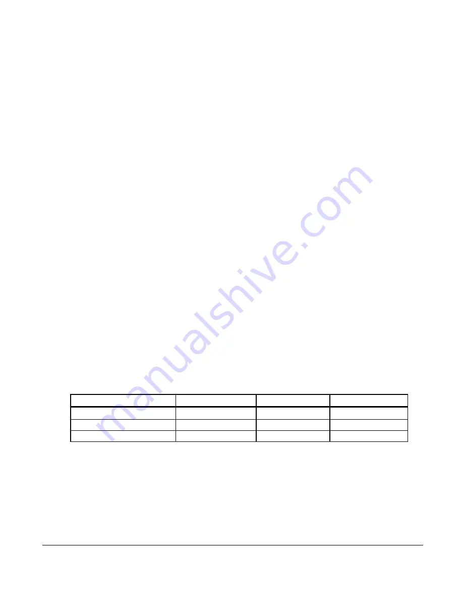
PLEASE NOTE: WHEN ORDERING PARTS, INDICATE THE SERIAL NUMBER OF COMPRESSOR
Machine Size (CFM / PSI)
Engine
(III)
Fan
(IV)
Unit
(V)
900 / 350
02250125-778
02250092-462
02250091-756
1150 / 350
02250124-731
02250136-317
02250104-038
1350 / 350
02250142-622
02250136-317
02250119-215
Summary of Contents for 1350XH
Page 6: ......
Page 18: ...Section 2 DESCRIPTION 12 Figure 2 3A Control System 900XH 1150XH and 1350XH Models...
Page 19: ...Section 2 DESCRIPTION 13 Figure 2 3B Control System Aftercooled Models...
Page 29: ...Section 2 DESCRIPTION 23 Figure 2 7 Wiring Diagram 02250145 161R01...
Page 30: ...NOTES 24...
Page 33: ...Section 3 SPECIFICATIONS 27 02250135 977R03 Figure 3 2 Identification Compressor Assembly...
Page 34: ...NOTES 28...
Page 38: ...NOTES 32...
Page 54: ...Section 7 ILLUSTRATIONS AND PARTS 48 02250127 622R08 7 3 ENGINE AND COMPRESSOR MOUNTING...
Page 56: ...Section 7 ILLUSTRATIONS AND PARTS 50 02250127 622R08 7 3 ENGINE AND COMPRESSOR MOUNTING...
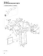
Page 58: ...Section 7 ILLUSTRATIONS AND PARTS 52 02250136 060R02 7 4 AIR INLET SYSTEM ALL MODELS...
Page 60: ...Section 7 ILLUSTRATIONS AND PARTS 54 02250136 060R02 7 4 AIR INLET SYSTEM ALL MODELS...
Page 62: ...Section 7 ILLUSTRATIONS AND PARTS 56 02250136 062R02 7 5 EXHAUST SYSTEM ALL MODELS...
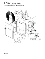
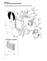
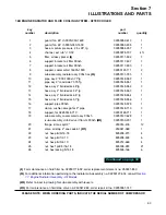
Page 72: ...Section 7 ILLUSTRATIONS AND PARTS 66 02250127 633R02 7 7 ENGINE RADIATOR ASSEMBLY ALL MODELS...
Page 74: ...Section 7 ILLUSTRATIONS AND PARTS 68 7 8 AFTERCOOLER MOUNTING ALL MODELS 02250150 135R03...
Page 82: ...Section 7 ILLUSTRATIONS AND PARTS 76 02250140 983R01 7 12A INLET VALVE AND PARTS 6 5 900XH...
Page 86: ...Section 7 ILLUSTRATIONS AND PARTS 80 02250054 762R06 7 13A INLET VALVE PARTS 6 5 900XH...
Page 90: ...Section 7 ILLUSTRATIONS AND PARTS 84 02250127 667R10 7 14A DISCHARGE SYSTEM 900XH AND 1150XH...
Page 96: ...Section 7 ILLUSTRATIONS AND PARTS 90 02250148 288R01 7 14C DISCHARGE SYSTEM 1350XH AFTERCOOLED...
Page 98: ...Section 7 ILLUSTRATIONS AND PARTS 92 02250148 288R01 7 14C DISCHARGE SYSTEM 1350XH AFTERCOOLED...
Page 116: ...Section 7 ILLUSTRATIONS AND PARTS 110 02250164 870R01 7 19 MINIMUM PRESSURE CHECK VALVE...
Page 118: ...Section 7 ILLUSTRATIONS AND PARTS 112 02250136 066R00 7 20 FUEL SYSTEM AND PARTS ALL MODELS...
Page 120: ...Section 7 ILLUSTRATIONS AND PARTS 114 02250127 727R01 7 21 ELECTRICAL PARTS ALL MODELS...
Page 126: ...Section 7 ILLUSTRATIONS AND PARTS 120 02250136 503R02 7 23 FRAME AND PARTS...
Page 128: ...Section 7 ILLUSTRATIONS AND PARTS 122 7 24 DECAL GROUP...
Page 130: ...Section 7 ILLUSTRATIONS AND PARTS 124 7 24 DECAL GROUP...
Page 132: ...Section 7 ILLUSTRATIONS AND PARTS 126 7 24 DECAL GROUP...
Page 134: ...Section 7 ILLUSTRATIONS AND PARTS 128 7 24 DECAL GROUP...
Page 136: ...Section 7 ILLUSTRATIONS AND PARTS 130 7 25 DECAL LOCATIONS 02250136 067R03...
Page 138: ...Section 7 ILLUSTRATIONS AND PARTS 132 7 25 DECAL LOCATIONS 02250136 067R03...
Page 140: ...NOTES 134...
Page 141: ......


