Section 1
SAFETY
1
1.1 GENERAL
Sullair Corporation designs and manufactures all of
its products so they can be operated safely.
However, the responsibility for safe operation rests
with those who use and maintain these products.
The following safety precautions are offered as a
guide which, if conscientiously followed, will mini-
mize the possibility of accidents throughout the
useful life of this equipment. Read the CIMA Safety
Manual prior to compressor operation and towing, if
applicable in your area.
The air compressor should be operated only by
those who have been trained and delegated to do
so, and who have read and understood this
Operator’s Manual. Failure to follow the instruc-
tions, procedures and safety precautions in this
manual can result in accidents and injuries.
NEVER
start the air compressor unless it is safe to
do so.
DO NOT
attempt to operate the air com-
pressor with a known unsafe condition. Tag the air
compressor and render it inoperative by discon-
necting the battery so others who may not know of
the unsafe condition will not attempt to operate it
until the condition is corrected.
Use and operate the air compressor only in full
compliance with all pertinent OSHA requirements
and/or all pertinent Federal, State and Local codes
or requirements.
DO NOT
modify the compressor except with written
factory approval.
Each day walk around the air compressor and
inspect for leaks, loose or missing parts, damaged
parts or parts out of adjustment. Perform all recom-
mended daily maintenance.
Inspect for torn, frayed, blistered or otherwise dete-
riorated and degraded hoses. Replace as required.
1.2 TOWING
(I)
A. PREPARING TO TOW
1. Prior to hitching the air compressor to the tow
vehicle, inspect all attachment parts and equip-
ment, checking for (i) signs of excessive wear or
corrosion, (ii) parts that are cracked, bent, dented
or otherwise deformed or degraded, and (iii) loose
nuts, bolts or other fasteners. Should any such con-
dition be present,
DO NOT TOW
until the problem
is corrected.
2. Back the tow vehicle to the compressor and posi-
tion it in preparation for coupling the compressor.
3. If the compressor is provided with a drawbar
latched in the vertical upright position, carefully
unlatch drawbar and lower it to engage the coupling
device. If not, raise drawbar to engage coupling
device or otherwise couple the compressor to the
towing vehicle.
Use the screw jack provided or a chain fall if you
cannot lift or lower it without avoiding injury to your-
self or others. Keep hands and fingers clear of the
coupling device and all other pinch points. Keep
feet clear of drawbar to avoid injury in case it should
slip from your hands.
4. Make sure the coupling device is fully engaged,
closed and locked.
5. If chains are provided, pass each chain through
its point of attachment on the towing vehicle; then
hook each chain to itself by passing the grab hook
over (not through) a link. Cross chains under front
of drawbar before passing them through points of
attachment on towing vehicle to support front of
drawbar in case it should accidentally become
uncoupled.
6. Make sure that the coupling device and adjacent
structures on the towing vehicle (and also, if uti-
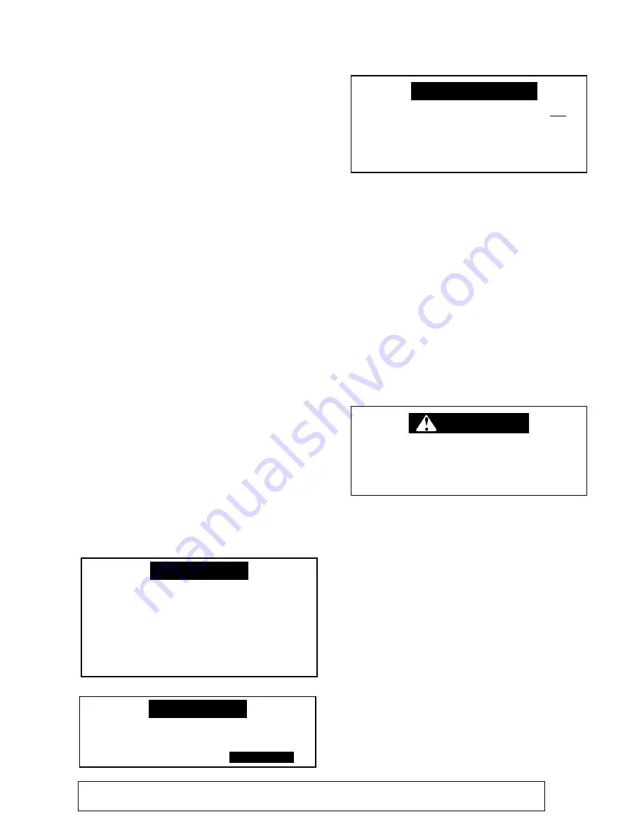
Estimated hose life based on a 5-day 8-
hour work week is 3 years. These con-
ditions exist on an 8-hour shift only.
Any other operation of the equipment
other than 8-hour shifts would shorten
the hose life based on hours of opera-
tion.
NOTE
This equipment may be tongue heavy.
DO NOT
attempt to raise or lower the
drawbar by hand if the weight is more
than you can safely handle.
(I)
While not towed in the usual sense of the word, many of these instructions are directly applica-
ble to skid-mounted portable air compressors as well.
WARNING
N
tow vehicle, as the vehicle may not
brake safely with excess weight. See
rated limit in tow vehicle Operator’s
Manual, and review its instructions and
other requirements for safe towing.
NOTE (cont.)
DO NOT
tow the compressor should
its weight exceed the rated limit of the
continued
NOTE
Summary of Contents for 1350XH
Page 6: ......
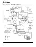
Page 18: ...Section 2 DESCRIPTION 12 Figure 2 3A Control System 900XH 1150XH and 1350XH Models...
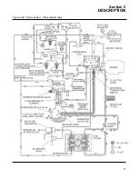
Page 19: ...Section 2 DESCRIPTION 13 Figure 2 3B Control System Aftercooled Models...
Page 29: ...Section 2 DESCRIPTION 23 Figure 2 7 Wiring Diagram 02250145 161R01...
Page 30: ...NOTES 24...
Page 33: ...Section 3 SPECIFICATIONS 27 02250135 977R03 Figure 3 2 Identification Compressor Assembly...
Page 34: ...NOTES 28...
Page 38: ...NOTES 32...
Page 54: ...Section 7 ILLUSTRATIONS AND PARTS 48 02250127 622R08 7 3 ENGINE AND COMPRESSOR MOUNTING...
Page 56: ...Section 7 ILLUSTRATIONS AND PARTS 50 02250127 622R08 7 3 ENGINE AND COMPRESSOR MOUNTING...
Page 58: ...Section 7 ILLUSTRATIONS AND PARTS 52 02250136 060R02 7 4 AIR INLET SYSTEM ALL MODELS...
Page 60: ...Section 7 ILLUSTRATIONS AND PARTS 54 02250136 060R02 7 4 AIR INLET SYSTEM ALL MODELS...
Page 62: ...Section 7 ILLUSTRATIONS AND PARTS 56 02250136 062R02 7 5 EXHAUST SYSTEM ALL MODELS...
Page 72: ...Section 7 ILLUSTRATIONS AND PARTS 66 02250127 633R02 7 7 ENGINE RADIATOR ASSEMBLY ALL MODELS...
Page 74: ...Section 7 ILLUSTRATIONS AND PARTS 68 7 8 AFTERCOOLER MOUNTING ALL MODELS 02250150 135R03...
Page 82: ...Section 7 ILLUSTRATIONS AND PARTS 76 02250140 983R01 7 12A INLET VALVE AND PARTS 6 5 900XH...
Page 86: ...Section 7 ILLUSTRATIONS AND PARTS 80 02250054 762R06 7 13A INLET VALVE PARTS 6 5 900XH...
Page 90: ...Section 7 ILLUSTRATIONS AND PARTS 84 02250127 667R10 7 14A DISCHARGE SYSTEM 900XH AND 1150XH...
Page 96: ...Section 7 ILLUSTRATIONS AND PARTS 90 02250148 288R01 7 14C DISCHARGE SYSTEM 1350XH AFTERCOOLED...
Page 98: ...Section 7 ILLUSTRATIONS AND PARTS 92 02250148 288R01 7 14C DISCHARGE SYSTEM 1350XH AFTERCOOLED...
Page 116: ...Section 7 ILLUSTRATIONS AND PARTS 110 02250164 870R01 7 19 MINIMUM PRESSURE CHECK VALVE...
Page 118: ...Section 7 ILLUSTRATIONS AND PARTS 112 02250136 066R00 7 20 FUEL SYSTEM AND PARTS ALL MODELS...
Page 120: ...Section 7 ILLUSTRATIONS AND PARTS 114 02250127 727R01 7 21 ELECTRICAL PARTS ALL MODELS...
Page 126: ...Section 7 ILLUSTRATIONS AND PARTS 120 02250136 503R02 7 23 FRAME AND PARTS...
Page 128: ...Section 7 ILLUSTRATIONS AND PARTS 122 7 24 DECAL GROUP...
Page 130: ...Section 7 ILLUSTRATIONS AND PARTS 124 7 24 DECAL GROUP...
Page 132: ...Section 7 ILLUSTRATIONS AND PARTS 126 7 24 DECAL GROUP...
Page 134: ...Section 7 ILLUSTRATIONS AND PARTS 128 7 24 DECAL GROUP...
Page 136: ...Section 7 ILLUSTRATIONS AND PARTS 130 7 25 DECAL LOCATIONS 02250136 067R03...
Page 138: ...Section 7 ILLUSTRATIONS AND PARTS 132 7 25 DECAL LOCATIONS 02250136 067R03...
Page 140: ...NOTES 134...
Page 141: ......


