Section 1
SAFETY
4
drawbar or if hinged, to raise it to the upright posi-
tion, by hand, if the weight is more than you can
safely handle. Use a screwjack or chain fall if you
cannot lift or raise the drawbar without avoiding
injury to yourself or others.
11. When possible, stow hinged drawbar in the ver-
tical upright position. Make certain it is securely
latched in the vertical upright position. Keep feet
clear of drawbar at all times to avoid crushing acci-
dents in case it should slip from your hands or oth-
erwise fall to the ground.
12. Move the towing vehicle well clear of the parked
compressor and erect hazard indicators, barri-
cades and/or flares (if at night) if compressor is
parked on or adjacent to public roads. Park so as
not to interfere with traffic.
1.3 PRESSURE RELEASE
A.
Open the pressure relief valve at least weekly to
make sure it is not blocked, closed, obstructed or
otherwise disabled.
B.
Install an appropriate flow-limiting valve between
the compressor service air outlet and the shutoff
(throttle) valve, when an air hose exceeding 1/2”
(13mm) inside diameter is to be connected to shut-
off (throttle) valve, to reduce pressure in case of
hose failure, per OSHA Standard 29 CFR 1926.302
(b) (7) or any applicable Federal, State and Local
codes, standards and regulations.
C.
When the hose is to be used to supply a mani-
fold, install an additional appropriate flow-limiting
valve between the manifold and each air hose
exceeding 1/2” (13mm) inside diameter that is to be
connected to the manifold to reduce pressure in
case of hose failure.
D.
Provide an appropriate flow-limiting valve for
each additional 75 feet (23 meters) of hose in runs
of air hose exceeding 1/2” (13mm) inside diameter
to reduce pressure in case of hose failure.
E.
Flow-limiting valves are listed by pipe size and
rated CFM. Select appropriate valve accordingly.
F. DO NOT
use tools that are rated below the max-
imum rating of this compressor. Select tools, air
hoses, pipes, valves, filters and other fittings
accordingly.
DO NOT
exceed manufacturer’s rated
safe operating pressures for these items.
G.
Secure all hose connections by wire, chain or
other suitable retaining device to prevent tools or
hose ends from being accidentally disconnected
and expelled.
H.
Open fluid filler cap only when compressor is not
running and is not pressurized. Shut down the
compressor and bleed the sump (receiver) to zero
internal pressure before removing the cap.
I.
Vent all internal pressure prior to opening any
line, fitting, hose, valve, drain plug, connection or
other component, such as filters and line oilers, and
before attempting to refill optional air line anti-icer
systems with antifreeze compound.
J.
Keep personnel out of line with and away from
the discharge opening of hoses, tools or other
points of compressed air discharge.
K. DO NOT
use air at pressures higher than 30
psig (2.1 bar) for cleaning purposes, and then only
with effective chip guarding and personal protective
equipment per OSHA Standard 29 CFR 1910.242
(b) or any applicable Federal, State and Local
codes, standards and regulations.
L. DO NOT
engage in horseplay with air hoses as
death or serious injury may result.
M.
This equipment is supplied with an ASME
designed pressure vessel protected by an ASME
rated relief valve. Lift the handle once a week to
make sure the valve is functional.
DO NOT
lift the
handle while machine is under pressure.
N.
If the machine is installed in an enclosed area it
is necessary to vent the relief valve to the outside
of the structure or to an area of non-exposure.
O. DO NOT
remove radiator filler cap until the
coolant temperature is below its boiling point. Then
loosen cap slowly to its stop to relieve any excess
pressure and make sure coolant is not boiling
before removing cap completely. Remove radiator
filler cap only when cool enough to touch with a
bare hand.
P.
The ethyl ether in the replaceable cylinders used
in diesel ether starting aid systems (optional) is
under pressure.
DO NOT
puncture or incinerate
those cylinders.
DO NOT
attempt to remove the
center valve core or side pressure relief valve from
these cylinders regardless of whether they are full
or empty.
Q.
If a manual blowdown valve is provided on the
receiver, open the valve to insure all internal pres-
sure has been vented prior to servicing any pres-
surized component of the compressor air/fluid sys-
tem.
1.4 FIRE AND EXPLOSION
A.
Refuel at a service station or from a fuel tank
designed for its intended purpose. If this is not pos-
sible, ground the compressor to the dispenser prior
Summary of Contents for 1350XH
Page 6: ......
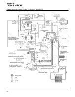
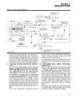
Page 18: ...Section 2 DESCRIPTION 12 Figure 2 3A Control System 900XH 1150XH and 1350XH Models...
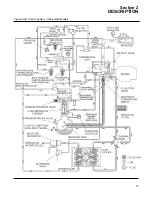
Page 19: ...Section 2 DESCRIPTION 13 Figure 2 3B Control System Aftercooled Models...
Page 29: ...Section 2 DESCRIPTION 23 Figure 2 7 Wiring Diagram 02250145 161R01...
Page 30: ...NOTES 24...
Page 33: ...Section 3 SPECIFICATIONS 27 02250135 977R03 Figure 3 2 Identification Compressor Assembly...
Page 34: ...NOTES 28...
Page 38: ...NOTES 32...
Page 54: ...Section 7 ILLUSTRATIONS AND PARTS 48 02250127 622R08 7 3 ENGINE AND COMPRESSOR MOUNTING...
Page 56: ...Section 7 ILLUSTRATIONS AND PARTS 50 02250127 622R08 7 3 ENGINE AND COMPRESSOR MOUNTING...
Page 58: ...Section 7 ILLUSTRATIONS AND PARTS 52 02250136 060R02 7 4 AIR INLET SYSTEM ALL MODELS...
Page 60: ...Section 7 ILLUSTRATIONS AND PARTS 54 02250136 060R02 7 4 AIR INLET SYSTEM ALL MODELS...
Page 62: ...Section 7 ILLUSTRATIONS AND PARTS 56 02250136 062R02 7 5 EXHAUST SYSTEM ALL MODELS...
Page 72: ...Section 7 ILLUSTRATIONS AND PARTS 66 02250127 633R02 7 7 ENGINE RADIATOR ASSEMBLY ALL MODELS...
Page 74: ...Section 7 ILLUSTRATIONS AND PARTS 68 7 8 AFTERCOOLER MOUNTING ALL MODELS 02250150 135R03...
Page 82: ...Section 7 ILLUSTRATIONS AND PARTS 76 02250140 983R01 7 12A INLET VALVE AND PARTS 6 5 900XH...
Page 86: ...Section 7 ILLUSTRATIONS AND PARTS 80 02250054 762R06 7 13A INLET VALVE PARTS 6 5 900XH...
Page 90: ...Section 7 ILLUSTRATIONS AND PARTS 84 02250127 667R10 7 14A DISCHARGE SYSTEM 900XH AND 1150XH...
Page 96: ...Section 7 ILLUSTRATIONS AND PARTS 90 02250148 288R01 7 14C DISCHARGE SYSTEM 1350XH AFTERCOOLED...
Page 98: ...Section 7 ILLUSTRATIONS AND PARTS 92 02250148 288R01 7 14C DISCHARGE SYSTEM 1350XH AFTERCOOLED...
Page 116: ...Section 7 ILLUSTRATIONS AND PARTS 110 02250164 870R01 7 19 MINIMUM PRESSURE CHECK VALVE...
Page 118: ...Section 7 ILLUSTRATIONS AND PARTS 112 02250136 066R00 7 20 FUEL SYSTEM AND PARTS ALL MODELS...
Page 120: ...Section 7 ILLUSTRATIONS AND PARTS 114 02250127 727R01 7 21 ELECTRICAL PARTS ALL MODELS...
Page 126: ...Section 7 ILLUSTRATIONS AND PARTS 120 02250136 503R02 7 23 FRAME AND PARTS...
Page 128: ...Section 7 ILLUSTRATIONS AND PARTS 122 7 24 DECAL GROUP...
Page 130: ...Section 7 ILLUSTRATIONS AND PARTS 124 7 24 DECAL GROUP...
Page 132: ...Section 7 ILLUSTRATIONS AND PARTS 126 7 24 DECAL GROUP...
Page 134: ...Section 7 ILLUSTRATIONS AND PARTS 128 7 24 DECAL GROUP...
Page 136: ...Section 7 ILLUSTRATIONS AND PARTS 130 7 25 DECAL LOCATIONS 02250136 067R03...
Page 138: ...Section 7 ILLUSTRATIONS AND PARTS 132 7 25 DECAL LOCATIONS 02250136 067R03...
Page 140: ...NOTES 134...
Page 141: ......


